Bob is a service technician who is well trained and nationally certified. However, he has sometimes suffered from the same confusion that all technicians occasionally do — the facts that he gathers may or may not point to the obvious cause of the problem or the best solution. But Bob has had something that no one else has. He recalled his long-time HVACR mentor and imagines him accompanying him as “Btu Buddy,” someone who reminded him to take time to stop and think before rushing to judgment, helping keep him on the right track, even with facts that are confusing.
Now, Bob’s company has promoted him to help train a new employee, right out of a school specializing in HVAC, just like Bob was. Bob is now Tim’s Btu Buddy. Tim is anxious to travel with Bob. Tim realizes that he is right out of school, with the theory and lab work that he accomplished in school, but still needs help. He knows that he worked with many of the components of the systems in the school, under ideal conditions with good light and air conditioning. Now it is into the field, sometimes under the house with poor lighting, or out on the rooftop in the sun, where the real action is. He is naturally and normally reluctant, but he has Bob to help guide him.
Bob and Tim were on their way to do routine annual service on a customer’s gas furnace and humidifier. Tim asked, “What are the things that we should look for that may cause problems on a gas furnace?”
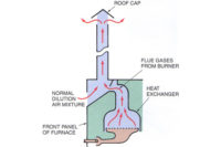
Bob said, “Gas as a fuel to heat air in a hot air furnace is very simple heat. The modern day burners do not require much service at all. In older furnaces that use cast iron burners, there are small passages that the air and gas mixture has to flow through and these small passages sometimes become restricted with dust and spider webs and have to be cleaned for proper air flow. The modern day end shot burners have large passages and the dust or debris just burns and goes up the flue (Figure 1).
Since the gas portion of the furnace is usually no problem, the service required with a standard gas furnace is fairly simple. It is mostly performed on the air side of the system, the blower and motor. Other furnaces that are super high efficiency require more thought. We will get into that later.”
Tim said, “Here we are. What do we do first?”
Bob said, “Let’s turn off the system at the furnace and set the thermostat to call for heat. Then we will go start the furnace with the furnace switch. Take off the furnace front panel so we can watch the burner light. This system has a spark igniter to light the pilot light, which in turn lights the main burner. We can watch the whole process. This three-step process assures there is adequate flame to ignite the burner, after proving the pilot light is lit.”
Tim said, “I realize that the pilot light should be lit before the main gas valve allows gas to the main burner, but how is the pilot light presence proven?”
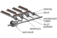
Bob explained, “When the spark ignites the pilot light, a flame rod that is mounted in the pilot light flame makes a circuit through the electronic circuit proving the flame is present (Figure 2). This is called a flame rectification system. Turn on the furnace and let’s watch it light.”
Tim turned on the switch and the spark igniter started sparking, the pilot light lit, but the main burner did not start. Tim asked, “What happened?”
Bob said, “The pilot light lit, but the main gas valve failed to open. I think that we either have a defective main gas valve or a fault in the electronics in the igniter. Let’s check out the simplest thing first. Turn off the system switch and ohm check the main gas valve coil.”
Tim checked the main gas valve with his ohmmeter by loosening the terminal to isolate the gas valve coil and placing the meter leads on the coil terminals. He said, “There is continuity through the coil. It looks good. Should we try to start the furnace again and see if the voltage is present after the pilot light is ignited?”
“Yes,” Bob said.
Tim fastened the terminal back to the gas valve and started the furnace again. He said, “There is no power getting to the gas valve coil. It will never start without power.”
Bob said, “I think that the next thing we should do is clean the flame rod and make sure its connections are solid and tight. There is only a very small amount of current flowing in this circuit and any resistance will not allow it to start.”
They removed the pilot light assembly and took the connection to the flame rod apart and cleaned the connectors. Bob then said, “Clean the flame rod surface with very fine sand cloth, blow all filings away, and assemble it again.”
They got the assembly back together and turned the furnace back on and it went through the process and the burner lit as it should. Bob said, “Everything looks normal now. Let the burner stay on until the fan starts and then set the thermostat back to normal and we will make sure the fan shuts down after cooling the furnace down.”
Tim asked, “Shouldn’t we oil the fan bearings and look over the fan?”
Bob said, “Yes, after the furnace cools.”
They waited until the fan stopped running and shut the furnace off at the system switch. They then removed the fan door and fan from its compartment. They oiled the bearings and examined the fan wheel for dirt when Tim said, “The fan wheel is clean, and it seems that the filters have been maintained correctly.”
Tim took his flashlight and examined the evaporator coil that is used for cooling and said, “The coil surface is very clean. I think this system is ready to go another year.”
Tim replaced the air filter and put the furnace back together and then said, “Now comes the humidifier. What special things should we know about it?”
Bob said, “This is a bypass type of humidifier. It is mounted on the supply duct in this installation. Air from the supply is in a positive pressure and is pushed into the humidifier body. The return duct is in a negative pressure and it is connected to the outlet side of the humidifier. The pressure difference creates hot airflow. The humidifier has a wet surface area that causes evaporation of the liquid water to a vapor, which is pulled into the furnace return air stream and adds humidity to the whole duct system and house. The surface area may be porous plates that act like a wick to keep the surface area wet or it may be a rotating wire drum that keeps liquid water in contact with the air stream. In either case, there is standing water that is evaporated. Any time there is evaporation, the minerals in the water stay behind in the puddle of water. The concentration of minerals increases more and more and these minerals coat the plates or wire and need to be cleaned or changed. There is a slight excess of water that goes down the drain. The excess of water helps keep the water reservoir from being over-concentrated with minerals.”
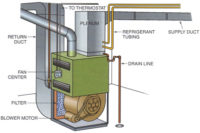
They disassembled the unit and Bob said, “This is an even different system; it dribbles water over a wire screen (Figure 3). The solenoid valve stops and starts the water flow. There is a slight excess of water and it goes down the drain. Let’s remove the screen and pan under it so we can clean it.”
They cleaned the evaporation portion of the humidifier and reassembled it and Tim said, “I think we are ready to start.”
They started the system and everything worked well. Tim asked, “How does the humidifier know when to stop and start?”
Bob said, “The best system has a humidistat to control the water flow to the humidifier. The most popular humidity level seems to be between 40 percent and 60 percent. The owner can set the desired condition. If the owner forgot to lower the humidistat setting in the summer, the humidifier would not have any capacity to evaporate water with summertime air temperatures so it wouldn’t be effective.”
Tim said, “Well, another day and another interesting lesson.”
Publication date: 11/17/2014
Want more HVAC industry news and information? Join The NEWS on Facebook, Twitter, and LinkedIn today!


