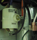
Figure 1 shows a PTCR wired in a circuit. Whenever a thermistor increases its resistance with an increase in temperature, it is said to have a positive temperature coefficient (PTC). If the thermistor decreases its resistance with an increase in its temperature, it is said to have a negative temperature coefficient (NTC).
Figure 2 illustrates graphs of resistance vs. temperature of both PTC and NTC coefficient resistors.

PTCR APPLICATIONS
PTCRs have been used in the HVACR industry for many years. They are made from a very pure semiconducting ceramic material.Because the PTCR has a positive temperature coefficient, resistance is very low over a wide range of low temperatures. However, when reaching higher temperatures, the resistance increases. These characteristics can be used when starting certain motors.
Many times, PTCR devices are used in place of potential or current-type starting relays. PTCRs can provide starting torque in permanent split capacitance (PSC) motors, when the condensing and evaporating pressures have been equalized somewhat during the off cycle.
The main advantage of this device is that it has no contacts, coils, or moving parts, thus requiring less maintenance. Also, it is simpler to troubleshoot.
WIRING IT IN
The PTCR is wired in parallel to the run capacitor. In other words, it is wired in series with the start winding and in parallel with the run winding. (See Figure 3.)When the cycling control closes, an inrush of starting current passes through the PTCR and the start winding because they are in series. This large starting current inrush happens because of the very low resistance of the PTCRs when they experience a low temperature. The starting current can actually bypass the run capacitor because it passes through the PTCR (which is in series with a run capacitor).
One function of the run capacitor is to cause a phase shift between the run and start windings during the starting and run cycles, which creates a torque. However, the run capacitor also has the ability to limit current flow through the start winding during the running cycle because of its capacitive reactance. With the PTCR in parallel with the run capacitor, large amounts of starting inrush current can pass through the PTCR and start winding for more starting power.
This high starting current passing through the PTCR causes it to increase in temperature rapidly. In less than half a second, the PTCR quickly increases in resistance, which pretty much stops the current flowing through it. The motor should now be up to speed and acting much like a PSC motor, with the run capacitor in series with the starting winding and in parallel with the run winding.
As long as there is voltage on the motor circuit, the PTCR stays hot and thus has very high resistance. It is actually out of the circuit when hot, and has no function but to block current through itself.
TIME DELAY
Time delays are often designed into systems with a PTCR. This time delay is important to allow the PTCR to cool down to its initial temperature (low resistance) before the next motor restart. The PTCR must be cooled down; otherwise, the high current inrush or starting power may not last long enough for effective motor starting.Many ice-making systems that employ a PTCR on their PSC compressor motors use a built-in, forced-off time from 2 to 3 minutes. This forced time delay, employed each time the compressor is cycled off (usually from a full bin), allows for a cool-down period for the PTCR.
Some equipment manufacturers design a control scheme that energizes a solenoid during the off cycle. This solenoid allows pressures to equalize between high (condensing) and low (evaporating) pressures for easier starting. Ice machine manufacturers can simply energize the hot gas solenoid during the off cycle for pressure equalization purposes.
TROUBLESHOOTING
The PTCR can be checked out easily. All you need is an ohmmeter.After examining the PTCR for cracks and making sure it is cooled down to room temperature, measure the resistance of the PTCR with your ohmmeter. Place the ohmmeter between both end tabs, or between one end tab and the center tab of the PTCF, depending on its design. (See Figure 4.)
Record the room temperature value; compare it with manufacturer’s specifications for a resistance range. If the resistance falls outside of the manufacturer’s range of resistance, discard the PTCR and install a new one.
SAFETY NOTE
The surface of the PTCR will reach more than 200 degrees F when voltage has been applied to it. Take care when handling this device to prevent burns.Tomczyk is a professor of HVACR at Ferris State University, Big Rapids, MI, and the author of Troubleshooting and Servicing Modern Air Conditioning & Refrigeration Systems, published by ESCO Press. To order, call 800-726-9696. Tomczyk can be reached at tomczykj@tucker-usa.com (e-mail).
Publication date: 07/01/2002

