Sometimes it is advantageous to use more than one fan in a system. The fans may be located in close proximity to each other such as mounted on a common shaft, or separated by quite a distance such as a supply and exhaust fan. Most often there is some compelling reason to use more than one fan in a single system.
1.One fan may be too large and not fit into the desired space, or it may weigh too much if supported on upper levels.
2.The required operating range of the system may necessitate multiple fans instead of one large fan controlled over a wide operating range. Multiple fans for capacity control may be more economical if cost of operation is critical, especially at very low flow rates for long time intervals.
3.Supply and exhaust fans operating on opposite ends of a system decrease the pressure buildup in a duct or space compared to a single fan. It is usually easier to control a zero point location or maintain low pressures (such as the draft over a fire in a boiler) if supply and exhaust fans are used.
4.Critical systems are often equipped with redundant or backup fans in case of a fire or accident in a tunnel or some other emergency that requires a sudden increase in flow. Redundant fans are also used to eliminate downtime during fan maintenance.
5.Some systems for process applications may require pressures that are greater than a single fan can produce or when noise may be a special concern. When this occurs, two fans are placed in series with each taking about one-half of the pressure.

Two fans in series. (Click on the image for an enlarged view.)
RATING TWO FANS IN SERIES
Two fans in series are normally rated as a single unit in order for AMCA rating definitions and practices to apply. To simplify selection and control, two fans of the same size are typically used with the required flow rate defined by the inlet conditions of the first fan. The combined total pressure across both fans will be the sum of the individual total pressure of each fan. Total pressures are used instead of static pressure because the fans can actually be different sizes and a change in fan or connecting duct areas has an influence upon static pressure values.There may also be bypass ductwork around the second fan if only one fan is run for a period of time. These losses must be added to the normal system resistance requirements.
What is the quickest and easiest way to select two fans in series?
1.Establish the system requirements in terms of total pressure. If they are known only in terms of static pressure, total pressure values may be calculated by adding the velocity pressure corresponding to the velocity passing through the outlet of the second stage fan to the system static pressure requirements.
2.If axial fans or inline fans are being considered, select each fan for the flow rate required and one-half of the system total pressure requirements. If centrifugal fans are being considered, select each fan for the flow rate required and one-half of the system total pressure requirements plus an allowance for interconnecting ductwork losses, typically one inch of total pressure.
It must be realized that the above selection process is approximate in that the actual individual performance of each fan is not the same. Both fans will handle the same mass flow of air but not volumetric flow rate. This is the result of differences in the inlet densities of each fan caused by differences in the inlet absolute pressures and differences in the temperatures resulting from the possible heat of compression or motor heating, etc., by the first stage fan.
The greatest significance is that the rating process can be simplified by making sure the system requirements are in terms of total pressure and that the fans are selected using total pressure.

Two fans in parallel. (Click on the image for an enlarged view.)
RATING FANS IN PARALLEL
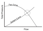
In most instances fans in parallel will be in some form of plenum application. Unlike fans in series when typically only two fans are involved, parallel fan applications may use multiple fans. In this case the selection process is straightforward in that each fan will be selected for the same static or total pressure with the flow rate being the total flow divided by the number of fans. Use care when selecting fans in parallel to ensure that the system resistance remains on a stable portion of the fan curve at all times. This is particularly true when the fans have a pronounced surge area or a dip in the fan curve and some form of control is applied. A good rule of thumb is to ensure that the operating point with all fans running is no higher than the lowest pressure in the dip. This minimizes the possibility that the fan will hunt back and forth across the peak of the curve looking for an operating point. This policy also minimizes the likelihood that the fans will experience unequal loading causing differences in motor load or creating unequal velocity profiles within the plenum which may result in a system effect.
ADDITIONAL CONSIDERATIONS
When a system depends upon more than one fan for proper operation, consideration must be given to those times when only one fan is running. This may be during start-up, during repairs, or as part of a flow control scheme based upon the number of fans running.1. Start-up conditions- In general, as long as the system curve and the fan curve always intersect at a stable operating point, no problem should be encountered during start-up or during continuous operation. Centrifugal fans or fixed pitch vane axial fans should be able to be started individually or together. It may be advisable to close inlet vanes or dampers during start-up to minimize horsepower requirements. Once the fans are up to speed, the controls may be opened.
Variable pitch vane axials, which have a dip in the fan curve, should be started with the blade pitch reduced and then opened up once at speed. If the first vane axial has been started, it is best to reduce its blade pitch and start the next fan at the same pitch. When both fans are up to speed and aerodynamically balanced, increase the blade pitch of both fans to the desired operating condition.
Fans in parallel should have some form of isolation damper to prevent the air from an energized fan from going back through a fan that is not energized. The damper also serves to minimize the shock during start-up of bringing a windmilling fan to a stop and then up to speed again. This is not good for the fan, motor, or system. A mechanical backstop clutch can also be used to eliminate windmilling of fans installed in parallel.

Vane axial fans in parallel and double width centrifugal fans in parallel. (Click on the image for an enlarged view.)
2. Continuous operation with one fan- All equipment will need periodic maintenance and repair. This means that at least one fan is shut down while the others are running. For fans in parallel equipped with isolation dampers, this is generally no problem. The motors of the fans left running must be sized properly by taking into account the shape and slope of the horsepower curve further out to the right. With fewer fans running, the system line will intersect the fan curve further out to the right than with all the fans running. As an example, with a vane axial fan the power may drop off but with a forward curved fan the power will increase due to the constantly rising horsepower characteristic.
For close-coupled fans in series, it is not advisable to run one fan with the other off. Obviously, an isolation damper will stop the air entirely. Without an isolation damper, the fan shut down will windmill, but the pressure drop across it when added to the reduction in pressure having only one fan running will likely make the system useless.
SUMMARY
When more than one fan is used in a system, whether in series or parallel, the following questions must be answered.• What is the relative location of the rating point on each fan curve under all operating conditions? Does the operating point remain on a stable portion of the curve?
• Does the location of the rating point allow the use of the fan control desired and the range of flow desired?
• Taking into account the range of operation and numbers of fans, do the motors satisfy the power required?
• Are there properly designed isolation dampers or other provisions in case some fans are shut down? Are leakage requirements satisfied?
• Are the system requirements satisfied under all operating conditions?
• Are sound levels acceptable under all operating conditions?
Satisfactory applications require satisfactory answers to all of the above.
Reprinted with permission from Greenheck’s Engineering Update, Volume VI Issue I. For more information, visit www.greenheck.com.
Publication date:01/21/2008


