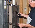
Measuring airflow at the equipment is the first step after checking the filters and blower for cleanliness in the commissioning process. Low airflow will cause low capacity and high energy bills. High airflow will result in poor humidity removal.
As energy costs continue to rise and our electrical infrastructure is strained to its limits, the practice of assessing equipment and system performance, in addition to the relatively new practice of whole-house residential building commissioning, will drive technicians to measure actual operating capacity of the equipment they are installing.
Tests include blower door testing, to verify the integrity of the envelope (home); duct tightness testing, to verify the integrity of the ducting system; proportional balancing; thermal imaging; and other industry-recognized testing to ensure that the Btus are developed - delivered and kept - in the conditioned space.
Let’s face it: Homes are dynamic. Any change to the structure, no matter how small, can affect the indoor environment. HVAC systems have a tremendous impact on housing or building performance, so their proper operation is critical.
The impact is so significant, that it is leading utilities, building scientists, and the weatherization community into the realm of HVAC system performance evaluation. Contractors that cannot measure system performance may find themselves at odds with these communities in a somewhat defenseless position.
Simply put: HVAC performance testing is quickly becoming a necessity.
WHAT ARE YOU SELLING?
Capacity and efficiency go hand-in-hand when it comes to air conditioning performance. You simply cannot have one without the other. Digital instruments may make you faster and exponentially more accurate when commissioning HVAC equipment. However, at the end of the day, how do you measure the performance, which, in most cases, is what you actually sold to your customer?Performance testing opens a new realm of diagnostic capability, whether it be for your own installations, or your competition’s. It also opens a new revenue stream of potential business that is not only lucrative, but one that produces visible and sustainable results for your customers.
Thousands of new and existing pieces of cooling equipment are installed and serviced each year without ever knowing if they are operating at or delivering their designed and/or rated capacity. Operational measurements are made to verify temperature drops, airflow, superheat, and/or subcooling, but often the total system performance is never quantified.
Equipment is sized for a minimum delivery, yet usually never tested after installation for actual performance verification. Equipment performance testing should be the final step of the commissioning process and the first step for accurate equipment troubleshooting. Equipment capacity testing validates all of the preliminary data measured (specifically refrigerant charge and airflow) during the system commissioning process by verification of the final equipment and total system performance.
Equipment performance and system performance are two different things, and it is imperative that the contractor understands the difference between them.
When referring to air conditioning, equipment performance refers specifically to the equipment. Is it producing its rated capacity? This is a charge- and airflow-dependent factor. On the other hand, system performance refers to the Btus of heating or cooling developed by the appliance, delivered to the conditioned space. System performance accounts for the duct leakage and thermal gains or losses that the duct system may experience. Measuring the capacity is simply a verification of the Btuh the equipment is producing. It is not a measure of efficiency (such as SEER or COP), which cannot be field calculated.
Normally, capacity is only one of the measurements required to calculate any of the Department of Energy (DOE)-recognized efficiency calculations. The equipment will produce its rated capacity only when operating at its optimal efficiency. Any adjustment or deficiency in equipment operation outside of design will degrade capacity and efficiency proportionally.
If you think 13 SEER hasn’t been a challenge, it may be time to think again. Many consumers are not realizing the substantial dollar savings promised. Systems are plagued with humidity control problems and a host of other performance-related issues have manifested. With the changes in equipment design and operating characteristics, contractors can take the proverbial rules of thumb they have been using and throw them out the proverbial window. Satisfactory operation of high-efficiency systems is totally dependent upon proper equipment selection, installation, and final commissioning procedures, including performance testing.
It is imperative that the equipment is always set up to the manufacturer’s specifications, including proper airflow and correct refrigerant charge. If these procedures are carefully followed and accurate instrumentation is used to verify the initial measurements, equipment operation will surely produce the manufacturer’s specified results.
Equipment does and will operate with differing capacities under different load conditions. However, the rated capacity under these conditions is normally stated by the manufacturer in the engineering data available for each specific piece of equipment, including the condenser, air handler, and coil combination. Nominal capacities and actual capacities do vary. Therefore, the rated capacity for the load conditions should always be verified against the actual field-measured capacity.

In a properly designed system, if all velocities are equal, cubic feet per minute (cfm) delivered is dictated by the branch and register size. Air velocities under 450 cfm are considered too low and will stratify. Air velocities over 750 cfm are considered too noisy for residential requirements.
EQUIPMENT CAPACITY
Equipment capacity is simply the measured output of the appliance at the appliance. It does not consider thermal losses or gains by the duct system or duct leakage. It is the benchmark of equipment performance and must always be measured prior to assessing total system performance.Equipment can perform at its optimal capacity and efficiency on a leaky or poorly designed duct system. The overall system efficiency and air delivery will be substandard, but it is not indicative of the equipment performance. This is of particular interest to the manufacturer, as equipment will, almost without exception, perform as listed on a properly designed system.
When referring to equipment, it should be understood that equipment can operate properly independent of the duct system, which is required for air delivery to the space. A poorly designed duct system can be the root cause of poor equipment performance. However, poor equipment performance is usually not the cause of poor system performance if the equipment is properly selected, commissioned, and maintained. The technician, designer, and/or salesman can be confident that listed equipment will perform as stated in the manufacturer’s literature.
The key to proper performance is twofold: the duct system must be designed for the blower performance curves and the addition of external airside devices must be limited to the available static pressure. Third-party verification of equipment performance through the listing agency validates the manufacturer’s performance claims.
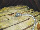
From the register, this run appeared to be 6-inch diameter, but a view from the attic shows otherwise. Bottom line: You cannot adjust and fix a poor design.
VERIFYING EQUIPMENT PERFORMANCE
Performance verification must start with the medium being conditioned. For most of the country, the medium is air. For equipment capacity calculation, a vane anemometer is ideal to measure airflow as it is a nondensity dependent measure of the air velocity.Vane anemometers have several advantages over any other method. The primary advantages are speed, accuracy, and ease of use. Vane anemometers do not require air density compensation due to air temperature, humidity, or atmospheric pressure.
The mini vane allows for a full duct traverse with an automatic calculation of the cubic feet per minute (cfm) in the duct if the dimensions are input into the instrument before the measurement is taken. As with any airflow measurement, it is imperative that the ducting is securely attached and sealed to the appliance, and the base pan (if side return is used) is sealed.
Air leaks upstream from where the measurements are made will significantly alter the actual reading obtained with this method. If done carefully, the measurement error will be less than 3 percent and easily as little as 1 percent. Due to the mini-vane’s aerodynamic design, changes of up to 10 percent in yaw and pitch of the probe head in the duct will result in less than 1 percent error in the measurement, making this the ideal probe for air measurement in the field.
Because of the complexity of accurate field measurement and inaccuracies associated with traditional measurement procedures, particularly in airflow and humidity, the capacity measurement obtained with a precision vane anemometer should be considered the reference measurement against which others, field and lab methods, can be compared in real-world applications. Again, air is never “standard air” (68°F, 0 percent rh, 29.92-inch Hg). The standard air equations like those used in the temperature rise method cannot be applied to obtain the high degree of accuracy often desired and achievable with a vane.
If using the standard air equations to compare measurements made with a vane, the constants in the standard air equations must be recalculated and the air measurement must be compensated for fan air inlet density. Air measurements made via a Pitot tube, hotwire, or flow grid will have significant error if the air density is not considered and corrected. Because of the complexity of accurately using these instruments to measure airflow the time required, and the low velocities often encountered, the vane is a perfect choice for residential air measurement.
ENTHALPY, TOO
With an accurate measure of airflow, all that is left is determining the change in enthalpy. Enthalpy is determined by measuring humidity and temperature. Because a very accurate reading is required, a precision humidity sensor is a must. Humidity measurements made external to the appliance with sling psychrometers and less sophisticated digital equipment can produce significant error due to improper technique: proper sling/air velocity, distilled water, clean wicks, etc.Enthalpy is total heat, and will account for both the latent and sensible loads. To keep it simple, it is not absolute enthalpy we are looking for but the change in enthalpy or Δh. A pocket humidity stick that will insert into the airstream in the duct is all that is needed.
This is one case where repeatability and precision are more important than absolute accuracy. Because we are looking for the change, if the same instrument is used for both readings, the error will be identical on both sides of the coil and will factor out completely. If the technician measures the entering and leaving wet bulb and dry bulb across the evaporator coil, a reference table or psychrometric chart will make quick work of the final calculation.
Remember, all that is needed to calculate capacity is entering and leaving wet bulb and dry bulb along with an accurate measure of airflow in cfm.
Real-time capacity testing requires even less effort and offers the advantages of speed, accuracy, and simplification of the calculations. Using a performance test kit (for example, the Testo 435) makes the heating and cooling capacity calculation a dynamic calculation. Airflow, air density, and enthalpy are all accounted for simultaneously to provide a real-time capacity calculation. Btuh, cooling tons, or kW can be directly calculated and displayed.
Utilizing wireless technology for temperature and humidity, and a mini-vane to measure airflow, make quick work of residential or commercial equipment commissioning. In most cases, the complete procedure can be performed in less than three minutes. When making measurements of equipment capacity, it is important to consider that no appliance will instantaneously perform at rated capacity. Usually six to 10 minutes of continuous and uninterrupted operation are required to reach steady-state efficiency. The time may be longer for higher mass heat exchangers, coils, and/or systems that are operating outside of their design conditions.
Usually when the discharge air temperature stabilizes in the cooling or heating mode, it is safe to assume that heat transfer is occurring at a constant rate. Also, it should be considered that heat is added by the blower motor in the form of resistive heating and may or may not affect the calculation depending on where the measurement is taken.
Capacity testing is not new. It is just new to the field. The formulas have been around since Willis Carrier. Changes in quality and accuracy of instrumentation, coupled with probes specifically designed for this application, are allowing for quick and highly accurate capacity measurement. What was only possible with lab instrumentation a few years ago is now possible with field-grade instrumentation.
The accuracy achievable by hand is just as good as that done with instrumentation that performs a dynamic calculation. The difference? Speed and documentation. Higher-end instrumentation will allow for the field-measured results to be printed via a wireless printer. Data can also be streamed via USB into a PC for further evaluation. Digital opens a whole new world of processing power, enabling the technician to use the data immediately to make pertinent evaluations and decisions.
Publication date:08/04/2008


