
Figure 1. The timer consists of six terminals, a motor to run the clock, and a defrost termination solenoid.
When a refrigeration system is designed to maintain a product temperature at or below the freezing temperature of water, there will always be a necessity for the system evaporator to be defrosted at some sort of interval (due to the fact that air may contain large quantities of moisture).
TYPES OF DEFROST
Many different means of defrost are used in commercial refrigeration. The types - chosen based on product temperature - include off-cycle, forced off-cycle, water spray, electric resistant heat, and hot gas defrost.In medium-temperature systems, where the product will be kept at between 33°F and upwards of 45°, both off-cycle and forced off-cycle are used. In off-cycle defrost, the defrosting of the evaporator is performed whenever the cold control (thermostat or low pressure control) is satisfied and the compressor is turned off. The evaporator fans continue to operate, blowing air through the evaporator quickly, causing the evaporator to warm up to the product temperature.
Because most short-term product storage will be maintained at between 33° and 38°, this temperature is sufficient to completely defrost most systems.
For some systems - due to age, inadequately sized systems, or frequent air changes because employees enter the box often - the cold control may not be satisfied as often as is necessary to give the system the opportunity to defrost completely. Once an evaporator begins to freeze up, its ability to remove heat from the product is greatly reduced, and it might become necessary to force the system to shut down the compressor, giving the evaporator the chance to clear off ice.
A simple, 24-hour timer may be used, to either break one or more of the electrical supplies to the compressor, or de-energize the compressor contactor coil. It should be set from 30 minutes up to an hour of off time during a period of low use, so as not to affect product temperature. Usually one defrost per 24-hour period is sufficient for this type of system.

Figure 2. The defrost termination-fan delay stat is wired in series with the defrost termination solenoid and the evaporator fans. During normal refrigeration operation, the stats’ contacts are in the down position, energizing the evaporator fans.
LOW-TEMP DEFROST
With low-temperature systems, where the product temperature is maintained below 32°, you need to add heat to the evaporator to ensure that the ice that has formed is completely removed at intervals, to ensure that the system is operating at peak efficiency, and to protect the compressor from floodback.At other times, the defrost is also important to ensure that compressor oil that has logged in the evaporator is warmed up from time to time, to allow it to be returned to the compressor, ensuring proper compressor lubrication. In these situations, the two most common methods of defrost are electric resistance heaters or hot gas defrost. The control design is essentially the same for both, and both means, when properly installed and maintained, will effectively clear the evaporator of ice.
What is more important is to understand how and why to properly install and set up the defrost timer to operate when required, and to terminate defrost when the ice has been completely removed. The standard or most common defrost timer consists of a 24-hour wheel with 12 threaded holes for installation of up to a maximum of four defrost initiation pins that come supplied with the timer.
The timer also has an inner wheel with a settable pointer that can be changed to give up to a maximum of 120 minutes of defrost time. This wheel is known as the fail-safe timer. In most cases this is not what will be the intended means of defrost termination; it’s there to ensure that defrost will never go beyond a predetermined amount of time. In most cases you will set this to a maximum of 20 minutes.
This timer consists of six terminals, a motor to run the clock, and a defrost termination solenoid (Figure 1).
With the most common timer, there will be a copper jumper between terminals 1 and 2. If necessary, this can be removed and discarded. You will note that the timer motor (T) is powered from terminals 1-2 and N; terminals 1-2 and 3 are normally open contacts; and terminals 1-2 and 4 are normally closed contacts.
Also, the defrost termination solenoid is between terminals 1-2 and the X terminal. The defrost termination solenoid is the intended means for terminating defrost, not the fail-safe setting of the timer as mentioned earlier. It is necessary that another control be supplied at the evaporator that is wired to the X terminal to facilitate defrost termination. This thermostat is known as the “defrost termination-fan delay stat,” which is an SPDT (single-pole double-throw) thermostat. When the defrost solenoid is energized, it trips the timer back into its normal at-rest condition, returning the system to refrigeration mode.
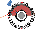
Figure 3. To correctly diagnose a failing defrost time clock, after the tech determines that the evaporator is indeed covered in ice, he should mark the timer’s outer wheel where the fail-safe pointer is, then wait about five minutes. Look at the timer face again; if the fail-safe pointer has moved away from the mark, this is not the problem.
DEFROST TERMINATION-FAN DELAY START
This control is very misunderstood; often when failed, it goes improperly diagnosed and is often not replaced. Let us look at how it is wired into the complete system and discuss its functions (Figure 2). You will note that the defrost termination-fan delay stat (DTFD) is wired in series with the defrost termination solenoid (DT) and the evaporator fans (EF).Now let’s look at what it does in a properly operating system. During normal refrigeration operation, the stats’ contacts are in the down position, energizing the evaporator fans. When the defrost timer initiates defrost, the two to four normally closed contacts open, de-energizing the compressor and the evaporator fans. The one to three normally open contacts close, energizing the evaporator heat (in this case electric resistance heaters). If this were a hot gas defrost system, the compressor would remain running, then the coil labeled CC would be the hot gas defrost solenoid.
During this period, heat is added to the back side of the evaporator, causing the ice to melt from it and drain out of the evaporator drain pan. During this period, the evaporator temperature cannot exceed 32° due to the rules of physics that all service techs learned during their early education in the industry. Once the evaporator is clear of ice, the evaporator will then begin to rise above 32° until it reaches the cut-in temperature of the defrost termination-fan delay stat, which would then close in the upward position, energizing the X terminal of the time clock (causing the system to return to refrigeration operation).
Notice at this time the evaporator fans would not be running. The purpose of this is misunderstood by many in the field. It is mistakenly believed that this is to ensure that heat from the defrosted evaporator is not blown out into the box, which would in turn warm the product. The actual purpose of the fan delay is to ensure that the remaining water that will be found on the evaporator due to capillary action is not blown out into the box, where it will contact and freeze to the product, the shelving, and the floor of the box, which could cause an unsafe and hazardous condition.
DEFROST FREQUENCY
In my years of teaching, I have often said that “less is more.” This is not the case with the defrost timer. I recommend that we utilize all four of the defrost pins and give the system the chance to defrost four times per day.When do we want this to occur? Look at the way a walk-in freezer is utilized to make this determination. Look at the operation of a normal restaurant that is open for three meals per day. Prior to each meal is when the freezer is going to see its highest use - or said another way, the times when the most people would be going in and out of it. Each time the door is opened there will be large air changes, which means the cool, dry refrigerated air will be replaced with warmer, moisture-laden air.
Since prep for breakfast would occur prior to 6 a.m., I recommend that a pin be installed at 6 a.m. Lunch prep would occur prior to noon, so the next pin be installed at 12 p.m. The same takes place in the afternoon before the evening meal, so the next pin would be installed at 6 p.m.
So far we have three defrost times. What about the last one? It is possible that during some of the earlier defrost times, the system would be placed back into refrigeration mode by the fail-safe timer prior to the evaporator clearing and the defrost was terminated by the defrost termination-fan delay stat. I recommend that the fourth pin be placed at the midnight position, which would give the system one additional defrost to clear the evaporator of any remaining ice found on it.
Now back to the reason why we don’t have too many defrosts using all four of the pins. If, during any of the defrost occurrences, the evaporator is clear of ice at the start of the call for defrost, the evaporator will quickly rise to the setpoint of the defrost termination-fan delay stat, returning the system to refrigeration mode.
TIMER TROUBLESHOOTING
Many service calls for a frozen-up evaporator are missed by the service tech due to impatience. During many of these calls, the tech turns the timer dial and causes it to trip into defrost mode. The evaporator is cleared of ice and the tech moves on to the next call.Often the cause of the frozen evaporator is that the timer motor, which through age has gotten weak and as it is approaching the defrost interval, no longer has enough torque to trip the timer into defrost. When the tech turns the timer, it proceeds to run properly again for a few days or a few weeks until it fails to function again. Figure 3 shows a method that only takes about five minutes to correctly diagnose a failing defrost time clock.
On arrival, after the tech has determined that the evaporator is indeed covered in ice, he should proceed to the timer and carefully mark the outer wheel at the point where the fail-safe pointer is. Then wait about five minutes or so, performing other tasks. Once this time has passed, look again at the timer face and see if the fail-safe pointer has moved away from the mark on the outer wheel. If it has moved, this is not the problem and the tech needs to look elsewhere. If the pointer has not moved, the timer motor is weak and the timer needs to be replaced.
Publication date:07/13/2009


