To spot missing insulation, use a fairly sensitive thermal imager with blended digital/thermal view. That’s because a) differences in temperature indicating a gap can be relatively small and b) while a gap may read clearly in infrared, finding the spot on the wall afterwards is difficult if you don’t have digital landmarks within the thermal view to go by. (Click on the image for an enlarged view.)
If capital expenditures at your customers’ facilities for new HVAC mechanical equipment have been frozen or eliminated, one way to free up financial resources is to tune up existing HVAC equipment. Follow best maintenance practices and the increased operating efficiency will reduce energy consumption. Cumulative energy bill savings can then supplement the general budget.
While HVAC systems vary widely in terms of equipment and operational characteristics, the following checklist should generally apply to most main equipment types and energy waste areas:
Steam system checklist:
• Insulation checks: Loose or missing insulation costs thousands of dollars in extra fuel costs per heating season. Use a thermal imager to inspect system insulation and identify insufficient areas.

If you don’t see a distinct temperature difference on either side of a steam trap, it may be failed and needs to be further investigated.
• Check air temperatures in boiler room: Proper combustion requires that the combustion air be between proper limits. Use a digital thermometer designed to measure ambient air temperatures and consider checking the carbon monoxide level in the boiler room, as well, to ensure safety.
• Other: In addition to the steps made above, also check the feedwater temperature, fuel oil heater temperature, and other items such as lubricant. These checks may not only save energy but also costs due to equipment repair or failure.

When taking readings near any combustion equipment, measure not only CO but CO2 and temperature as well.
• Electrical checks: Check compressor voltage and amperage to ensure that the motor is operating at manufacturer-recommended levels.
• Temperature checks: Check the temperatures of inlet and outlet air and water temperatures at heat exchangers to verify they are operating at their most efficient levels. Chilled water supply temperatures for most chilled water systems should be between 42° and 44°.
• Pressure checks: Use a digital multimeter with a pressure attachment to take the inlet and outlet pressures of shell and tube heat exchangers, to ensure the tubes are not fouled. Fouling will result in lower heat transfer and higher energy consumption at the compressor. Pressure drop across the heat exchanger (Delta P) may be anywhere from 5 psig to 25 psig and varies by manufacturer. Check refrigerant and pump pressures, as well, to ensure equipment is operating at baseline levels.
• Cooling tower checks: For cooling equipment to operate at its most efficient levels, the cooling tower must operate properly. Since cooling towers reject heat at a specific rate to the atmosphere, use a temperature/humidity meter to measure the outside air temperature and humidity and analyze cooling tower operation. Also measure the temperature of the condensing water supplied to the chiller. A common value is 85°.

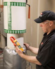
Some electrical test tools, such as this Fluke 902 Clamp Meter, offer temperature measurement too, making it easier to build in temperature checks.
• Electrical checks: Measure the voltage and amperage of the fan motor and compare to nameplate conditions.
• Temperature checks: Check the following values at air handlers:
- Outside air temperature
- Mixed air temperature
- Return air temperature
- Discharge or supply air temperature
- Coil face discharge air temperatures
- Space temperature sensors
- Economizer and related dampers
- Wet bulb temperature or relative humidity (rh) sensors
Take readings with a handheld temperature meter and compare them against those indicated by the control system to ensure accuracy. Sensor calibration should be an integral part of all maintenance programs.
• Air pressure checks: Check pressure drops across filter banks to ensure adequate airflow. Excessive pressure drops will cause higher than normal energy consumption. Measure air pressure drops across heating and cooling coils to ensure that the coils are clean. Measure the inlet and outlet air temperatures to ensure proper temperature rise or drop.
Lighting system checklist:
• Electrical checks: Thermography applications for lighting include ballast and breaker contact temperatures. Look for hotspots and compare values with baselines or previous temperature measurements for evaluation.
• Illumination levels: Use a light meter to measure foot-candle or lumen levels. Where possible, reduce illumination levels to industry standards. Especially consider reducing illumination during seasons when more natural light is available.
• Operational checks: Set up a recording meter to sample illumination levels during a facility’sunoccupiedhours. This will help identify areas where the lights are left on inadvertently or unnecessarily.

Hook a power quality monitor up to specific circuits and equipment, such as chillers, to determine energy consumption.
• Energy consumption checks: Use a power quality meter to evaluate your facility’s voltage, current, and kWh energy consumption. If possible, log energy consumption over time on specific circuits, and by specific equipment and areas. Compare your hourly usage rate to your utility fee structure and adjust usage patterns out of high-demand, high-cost times of day. Also check control system supply voltages to ensure proper controller operation. Controller communication bus values may be checked to ensure the integrity of the communication wiring.
• Control system: Check all sensors and indicating thermometers for properly calibrated gauges. Check valve and damper actuators as well. Actuator problems can cause higher than normal heating and cooling usage and high energy bills. Actuator output voltages and current signals can be checked using a regular digital multimeter.
• Temperature checks: Check the temperatures of inlet and outlet air and water temperatures at heat exchangers to make sure that they are operating at their most efficient levels. For example, chilled water supply temperatures for most chilled water systems are between 42° and 44°.
• Operational checks: Log air temperature over time, over occupied and unoccupied schedules, to identify areas left in the wrong temperature mode at night or on weekends, wasting energy.
• Setpoint checks: Check the accuracy of all temperature, pressure, and humidity control setpoints by logging those values over time. Control inaccuracy may waste 1 percent of energy per degree of error.
Reprinted with permission from the Fluke Application Note “Save Money With Best Practices and an Energy Inspection Checklist.” For more information, visit www.fluke.com.
Publication date:03/08/2010


