SUMMARY
This article, reprinted from an EXHAUSTO white paper, discusses the benefits of demand-controlled ventilation (DCV) systems in multi-story, multi-residential buildings, which include improving building energy efficiency, enhancing comfort and other key performance factors.DCV has a significant history of use in multi-story, multi-family buildings. This article reviews the application of DCV in new, retrofit and renovated building projects, and discusses the significant benefits associated with such practices - in particular, for high-performance ventilation, energy savings and comfort.
DCV is ideally suited for vertical subdivisions due to ease of installation and compliance with the latest building codes, particular those related to multi-story clothes dryer exhaust. More importantly, DCV enhances high-performance ventilation, as a result of quiet operation, reduced uncontrolled air infiltration and exfiltration - which can lead to improved indoor air quality (IAQ) - and substantial energy savings from reduced volumes of conditioned air exhausted and lower fan operating cost.
In terms of cost, a fixed speed ventilation system used with a clothes dryer can exhaust close to $800 of conditioned air annually, while a DCV system only exhausts $250. Similar differences can be found for bathroom and kitchen exhaust systems. Actual savings depend on location.
This article will examine general principles and recommended practices for selecting and designing DCV systems. It also reviews saving models that can be used to determine possible energy savings and ROI on retrofit projects.
In addition, an outline of performance expectations, such as durability, energy efficiency, sustainability considerations, and maintenance requirements is presented. Also presented are several case studies that highlight the real-world track record of DCV.
Properly specified and applied, DCV is shown to provide significant benefits for new construction and renovation projects.

Fig. 1: Building ventilation system showing location ventilation (ANSI/ASHRAE Standard 62.1 – 2007).
INTRODUCTION
Ventilation strategies for multi-story, multi-residential buildings (“vertical subdivisions”) are covered by the requirements for mechanical ventilation outlined in the American Society of Heating, Refrigerating and Air-Conditioning Engineers (ASHRAE) Standard 62.1. In recent years ventilation strategies have aimed to reduce the overall energy use of the building and to create a healthier, stimulating environment for the building’s occupants.For many years ventilation strategies have included constant outside air and economizer operation. Demand control ventilation is a relatively new concept. It has been around for decades and was pioneered in Europe where high energy prices created a natural market. Today, DCV systems are often associated with indoor pollutant control, where the pollutant is CO2, and CO2level control is the preferred method of control.
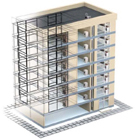
Fig. 2: Typical multi-story, multi-family appliance setup.
Typical applications are bathroom and kitchen ventilation, clothes dryer ventilation and ventilation and exhaust from boilers and mechanical rooms. The potential for energy savings in these applications is substantial, but designers often don’t consider this in calculating the building’s life cycle. And yet, they take “local” exhaust air volumes into consideration when determining building air supply rates. Fact of the matter is that local ventilation only exhausts conditioned air from a building and works against reducing energy usage. Thus it is very difficult to include local ventilation in efforts to recover energy because the exhaust can be contaminated with odor, grease, lint etc.

Fig. 3: Direct to the outside exhausted clothes dryers.
TYPICAL LOCAL VENTILATION SYSTEMS
We will look at three typical local ventilation systems: ventilation from clothes dryers, kitchen hoods and bathrooms.The applications are very similar and the ventilation or exhaust can be provided in one of three ways:
1.Exhaust via individual and mostly horizontal ducts to the outside of a building.The driving force is either a fan integrated in the appliance or/and an external booster fan that is interlocked with the appliance operation. (see Fig. 3)
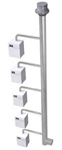
Fig. 4: Common shaft with constant speed exhaust system.

Fig. 5: Common shaft with DCV system.
When utilizing ‘direct-to-outside’ exhaust systems each appliance must have its own designated duct and booster fan. In a 10-story building this could add up to more than 100 boosters. Maintenance can be difficult and time consuming, especially for dryer venting systems. Lint or grease built-up on the outside wall can be difficult to remove or clean.

Fig. 6: Common shaft with sub-duct.
A common exhaust system must be ventilated by a fan that operates continuously. This is clearly stated in current building codes. The fan serves two purposes. It assures that whenever an appliance is used it is also being exhausted, and it directs the flow of a potential fire to the outside. For fire safety, each appliance’s duct connection into the common duct must have a sub-duct installed (see Fig. 6). The sub-ducts prevent a potential fire to spread to other stories.
When utilizing a common exhaust system it is unlikely that all users use all the appliances simultaneously. This means diversity factors can be applied to the duct design, saving space, materials and labor.
Common exhaust systems, like all location ventilations systems, have the potential for significant energy loss. A traditional system with an exhaust fan operating at full speed 24/7 can exhaust huge amounts of conditioned air. It only takes a visit to the rooftop to observe the exhaust flow - nice and cool in the summer and nice and warm in the winter - to realize energy is being lost.
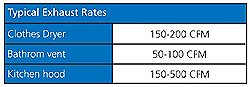
Table 1: Typical appliance exhaust rates.
Take the example of a 10-story building with four apartments per floor using a single fan for each of the three applications. That would add up to 40 x 175 cfm for the dryers, 40 x 75 cfm for the bathrooms and maybe 40 x 250 cfm or a total of 10,000 cfm. If the appliances are only used 30 percent of the time, the excess exhaust of conditioned air would be 7,000 cfm or10,080,000 cubic feet per day!
It seems obvious that there is a huge savings potential if using a DCV system.
But why not use a single speed fan with a relief damper?
The challenge in exhaust systems in multi-story buildings is avoiding negative pressure zones on the top floors of the building. That means that the pressure drop in the vertical shaft must be very low (0.1-0.2 inches wc). So, if the shaft is connected to a relief damper to the outside via a horizontal duct this duct can’t have any pressure drop. This makes it fairly large and costly.
You cannot pull air from a parking garage, because usually operates under negative pressure.
If the vertical shaft has a relief damper it is still conditioned air that is being pulled in most cases.
ESTABLISHING A MODEL TO QUANTIFY ENERGY SAVINGS IN LOCAL VENTILATION APPLICATIONS
It’s difficult to quantify the energy savings associated with a DCV system. However, recent studies in Canada have devised a calculation tool for clothes dryers than can also be used for kitchen and bathroom exhaust systems.A project by the Natural Gas Technologies Centre, Montreal, on behalf of Enbridge Gas Distribution, regarding the cost-effectiveness of switching from electric to natural gas-fired dryers discovered that there is a great potential for energy savings in vertical subdivisions and their laundry facilities. The data was collected from information in the open literature, laboratory test performances, and monitoring of laundries located in the greater Toronto area.

Table 2: Laundry utilization profile for 8-dryer laundry system.

Fig. 7: Test system setup.
In the laundry facilities, the dryers’ exhaust was collected in a plenum and vented to the outside by means of a single speed fan running 24 hour per day. The effect of using a variable-speed drive common exhaust fan, as opposed to a single-speed drive fan, was studied by conducting tests on a banks of multiple gas-fired and electrical dryers (see Fig. 7).

Table 3: Utilization profile and conditioned air savings.

Fig. 8: Utilization profile (graphic view).
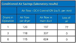
Table 4: Loss of conditioned air vs. number of dryers in operation and DCV control ON (laboratory results)

Table 5: Loss of conditioned air vs. number of dryers in operation and DCV control OFF (laboratory results)
The loss of conditioned air versus the number of dryers in operation can be seen in the following tables. It is clear that the loss of conditioned air is far higher without a demand controller (see Table 5) thanwitha controller (see Table 4).
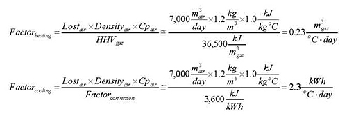
In order to calculate the potential energy savings, the heating and cooling factors (0.23 and 2.3) were derived from the following equations.


The Canadian study is significant because some of the results can be used in determining operating, heating and cooling losses, not only for dryers in laundry facilities, but also for multi-story clothes dryer and kitchen and bathroom applications.

Fig 9: Diversity factor vs. number of dryers served.
TIPS FOR DESIGNING A DEMAND CONTROLLED VENTILATION SYSTEM
DCV systems can be used both in new construction and for retrofitting. New construction offers more design flexibility and the potential for space and materials savings, but the potential for energy saving is virtually identical.The details of a DCV system design won’t be described here. However, we must consider some factors that have a major impact on the cost of operation.
By determining a utilization profile for a system, it is possible to establish a diversification factor. The diversity factor refers to the max. demand compared to the max. system capacity. A 70 percent diversity factor means that the total load will never exceed 70 percent of the maximum system capacity.
Fig. 9 has been designed from information in the open literature, and over 20 years of monitoring of multi-appliance ventilation systems.

Table 6: Utilization profile for shaft
However, please note that the diversity factor can’t always be used to reduce fan capacity. Some building codes or local jurisdictions will not allow this. When a diversity factor is not allowed as a means to reduce the fan capacity, the fan system must be designed to handle the total cfm of the appliances and overcome the total pressure within the exhaust system.
The utilization profile shown in Table 6 should be considered a conservative “worst-case-scenario.” With regard to kitchen and clothes dryer exhaust, the profile is likely dependant on occupancy levels. High-income households may reduce the utilization profile. Profiling bathroom usage depends on occupancy level as well.

Table 7: Energy cost, degree days and equipment efficiency used for calculations.
EXAMPLE OF SAVINGS FROM DEMAND CONTROLLED VENTILATION SYSTEMS
The following example is from an actual retrofit job in the State of Maryland.There is a total of 14 identical shafts in the condominium building. Each shaft is exhausting nine kitchen hoods - one on each floor of a nine-story building - with an exhaust fan mounted at the termination.

Table 8: Calculated savings for a single shaft with nine kitchen hoods and 1,560 cfm of exhaust flow.

Table 9: Calculated savings for a single shaft with nine kitchen hoods and 1,300 cfm of exhaust flow.
With a total number of 14 shafts, the estimated annual savings amounted to $42,644.

Table 10: Calculated payback for the retrofit job.

Fig. 10: Calculated payback for the retrofit job.
The estimated annual savings for the 14 shafts totaled $38,584.
The cost of 14 DCV systems amounted to approx. $55,000 while the installation cost amounted to approx. $16,000. With a total project cost of $71,000 the estimated payback was 22 months. The estimated simple 5-year return on investment (ROI) was 172 percent or 34 percent per year.
Upgrading from a constant volume system to a DCV system proved to be an excellent investment for the HOA.
OTHER ECONOMIC FACTORS TO CONSIDER
Both in new construction and in the retrofit market, there are economic factors to consider in addition to operational and energy savings.It is obvious that a reduction in the air exfiltration reduces the need for conditioned air infiltration. This will reduce the load on heating and cooling equipment, which can be reduced in size and result in further cost savings.
In some projects, the bathroom, kitchen and clothes dryer exhaust streams have been channeled through enthalpy heat recovery wheels. However, with an efficiency rating of 60-80 percent this is a much less efficient solution than efficiently controlling the exhaust rate.

Fig. 11: Pressure sensor probe location in a typical retrofit installation. (Click on the image for an enlarged view.)
Using a central DCV system vs. individual “direct-to-outside” vents can eliminate aesthetic issues such as the need for expensive architectural termination caps on the outside wall. Installation is simpler - it’s one fan vs. multiple fans with individual dryer interlock (required by building codes). It’s also less difficult to maintain, unlike wall-mounted systems which can be difficult to clean.
One should not ignore space savings either. Reducing shaft sizes can increase usable building space which can now be sold or rented. In a seven story building, reducing a shaft by 15 percent can represent as much as $3,000 in space cost.
DCV is perfect for retrofit projects. Because duct and fan connections and electrical power are already present, the only real challenges are integrating the exhaust fan controller and the pressure sensing devices. In most cases the controller can be installed near or on the fan. The pressure sensing device that is essential for the demand controlled fan speed modulation can be installed as shown in Fig. 11.
GUIDELINES FOR ESTIMATING POTENTIAL ENERGY SAVINGS ON A PARTICULAR PROJECT
The following procedure can be used to estimate energy savings when you replace a constant exhaust volume system with a DCV system.Estimate exhaust flow from appliances connected to the common duct.Locate a common shaft and its exhaust fan. If possible, measure the airflow in the duct. If that’s not possible, measure the airflow at the fan exit point. You can do this by using an anemometer to measure average fan exit velocities (fpm) and multiply it by the fan opening size (ft2). By multiplying the two values the airflow can be determined (cfm).
Determine utilization profile.If an actual utilization study is not available, use the profile found in Table 5.
Determine heating and cooling days for the location.They can be found online atwww.weatherdatadepot.com.
Calculate estimated energy savings from exhausting less conditioned air.Use the energy savings formula with actual heating and cooling degree days for the location to calculate the annual energy losses from exhausting conditioned air.
Calculate savings from reduced fan operation.Data may be available from the fan or motor manufacturer.
With the results, you can estimate return on investment and payback when utilizing a DCV system over a constant speed system.
EXPLANATION OF COMPONENTS IN DCV SYSTEMS
No two DCV systems are identical, so it is very important to review and evaluate the components. A DCV system should be fast and responsive and must be able to maintain a set-point with great accuracy and repeatability.A DCV system usually consists of the following components:
• An exhaust fan
• A variable speed controller
• A controller that monitors the exhaust demand via a pressure sensor and communicates with the variable speed controller or directly with the exhaust fan.
• A pressure sensor that senses shaft pressure changes, which are indications of demand changes.
Exhaust fan.The exhaust fan must be a true variable speed fan with a direct drive. Belt-driven fans are not suitable for modulating operation as speed variations add wear and tear to the belt. Noise is also a factor if belt-driven fans are used. It’s important that the fan is equipped with a true variable speed or inverter-duty motor. If not, the life expectancy is greatly reduced. Direct-drive motors are generally more reliable and require less maintenance.
It’s worth noting that the 2009 International Building Code prohibits the use of fans with motors located within the airstream for multistory clothes dryer installations.
Variable speed controller.The controller can be of a frequency drive design or a triac-based design. Most controllers are very basic with limited programming options. They can be connected and controlled directly with a pressure sensor, but it is not an optimal solution. This is explained further below. Triac-based solutions are mainly used with single phase 120VAC fans.
Pressure controller.As variable speed controllers don’t have many programming options, a DCV system should be based on a pressure controller. This controller is specifically designed to work with an external pressure sensor and communicate with a frequency drive or directly with a fan. It has a number of programming options and may be interlocked with the appliance operation. The PID loop is specifically designed for smooth and accurate operation - something that is difficult or impossible to obtain with a standard variable frequency drive.

Fig 12: Operating characteristics of a high-performance pressure sensor. (Click on the image for an enlarged view.)
The high-performance pressure sensor must be fine-tuned with the pressure controller’s PID loop. With the proper set-up, it is possible to maintain a +/-2 percent accuracy from the set-point. Simple systems with a variable frequency drive and a pressure sensor will typically work at a +/-20 percent accuracy. This type of inaccuracy leads to unnecessary fan speed adjustments and less energy savings. A fan that constantly changes speed will use more energy, create more noise and save a lot less by exhausting more conditioned air than necessary.
Eliminating the pressure controller may represent a minor savings up front, but the return on investment will decline dramatically and the payback will be extended.
Fig. 12 shows the operating characteristics of a pressure controller based system with a high-performance pressure sensor.
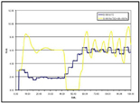
Fig 13: Operating characteristics of a standard pressure sensor. (Click on the image for an enlarged view.)
Fig 12 and 13 shows the operating characteristics of two differently controlled DCV systems when starting a fan from zero. The yellow curves show how well and how often the pressure sensor reads. The closer the distance is between vertical lines, the better it reads.
The blue curves show the quality of the signal sent to the variable speed controller. The flatter the curve is, the better the signal and fine-tuning of the pressure sensor versus the pressure controller. A curve as shown in Fig.13 indicates that fan hunting will be an issue and the system will be over-exhausted and under-exhausted on a regular basis.
It is also important to observe how fast the controller finds the set-point (see blue curves). The faster the better. In above examples, Fig. 12 finds the set-point in about 20 seconds where it takes about 60 seconds in Fig. 13.
The difference in operating characteristics of the two curves in Fig. 12 and Fig. 13 represents energy savings in favor of the system shown in Fig. 12. These savings can amount to as much as 20 percent, so an up front material savings can have a major negative impact on the payback and the ROI. Using our State of Maryland example, possible up front savings from using a standard pressure sensor probably amount to $5-6,000. If the inaccuracy of the standard sensor amounts to a 20 percent energy loss, the, the payback is now 26 months, the simple 5-year ROI is 138 percent and 27 percent annually. It is simply not worth going with a less sophisticated alternative.
LIFE-CYCLE AND MAINTENANCE BENEFITS OF DCV
Like all building system decisions, you must examine ventilation options based on a number of building characteristics. The main factors affecting the selection of ventilation system include: (1) design and environmental considerations, (2) installation and renovation logistics, (3) ongoing productivity and flexibility considerations, (4) ongoing maintenance, and (5) reclamation and after-use options.These factors describe themeasurable lifetime returnon a ventilation system. This is different fromlife-cycle cost analysis, or LCA, which may include a “cradle-to-grave” examination of the product’s anticipated use. Measurable lifetime return is a financial measurement similar tolifetime valueandreturn on investment (ROI), which describe the net cost advantage of employing a specific ventilation system.
To study LCA accurately requires significant investments in data gathering and analysis. Analyzing measurable lifetime return is more straightforward. The building team must study the life of the system in question, including its initial costs, installation requirements, typical maintenance measures, and disposal options. Basic financial information about the building where the system is used must also be known, such as cost of maintenance labor.
In general, DCV systems can provide an excellent measurable lifetime return because they tend to save a huge amount of energy and require little maintenance.
DCV LIFETIME RETURN
Given the importance of life-cycle considerations and measurable lifetime return in ventilation system selection, it is useful to assess the performance of ventilation systems in these fundamental terms.Studies show that DCV require less energy and maintenance cost over the life of the products:
Product description.As an example of these lifecycle advantages, EXHAUSTO’s DCV systems are engineered for heavy-use applications. The fans are made of heavy duty galvanized steel and insulated for lower noise levels. Motors are high-quality TEFC motors with inverter duty, variable speed, low-energy features. Typical applications include educational facilities (schools, colleges, etc.), hotels/resorts, sports facilities, and vertical subdivisions.
Preparation, installation and construction.The use of DCV can affect the cost of the construction or renovation phase. Less material may go into the construction of shafts and ducts. No special installation tools are required. Retrofit installations can usually take advantage of existing materials such as roof curbs and power supply.
Requirements for maintenance and operations.The DCV requires only minor maintenance costs such as regular cleaning of ducts and the fan interior. An access door that can be opened to provide full access to the fan casing and the duct makes cleaning easier. Direct-drive motors also eliminate the maintenance associated with belt-driven fans such as belt-replacement, belt-slippage, etc. Regular electrical power is required for the operation.
Building operations and human factors.DCV systems rarely interfere with the general building operation. The very low noise level improves occupant comfort dramatically over other ventilation options. DCV systems also reduce or eliminate problems with low pressure zones and draft, which further improves IAQ.
Reclamation, recycling and disposal.End-of-life scenarios for DCV systems include reclamation and recycling. Generally speaking all parts and components of fans can be recycled. The most significant advantage of DCV and most other ventilation systems is source reduction. The end-of-life impact is often very small as compared to the ability to reduce the source: newly manufactured ventilation products.

Fig 14: Lifecycle cost of demand controlled versus constant speed ventilation systems. (Click on the image for an enlarged view.)
Economic elements that impact the ventilation system investment are:
Cost avoidance
• Energy savings
• Product life-cycle increase
• Maintenance savings
Health & safety
• Air quality
• Thermal comfort
• Comfort
As shown in Fig. 14, over a 15 year period a typical demand controlled ventilation system serving eight dryers costs 55 percent less to operate than a constant speed system. In addition it saves 85 percent of the cost of exhausting conditioned air.
The graphs in Fig. 14 are based on 2009 energy prices. It is clearly the savings from exhausting less conditioned air that make the DCV system very attractive. But fan operating savings are attractive as well.
SUSTAINABILITY AND DCV
As awareness of sustainability and green building grows, so does the demand for products and projects which score points and ratings in the LEED Building Rating System created by the U.S. Green Building Council. Building teams that specify DCV can apply for points under the categories Energy & Atmosphere (EA), Indoor Environmental Quality (IEQ) and Innovation & Design Process (IP). Projects can acquire points as follows:Energy & Atmosphere (EA)
• Minimum energy performance
• Optimize energy efficiency
Indoor Environmental Quality (IEQ)
• Minimum IAQ performance
• Increased ventilation
• Controllability of systems, thermal comfort
• Thermal comfort design
DCV AND INCENTIVES
Because of the large potential for energy savings, DCV systems usually qualify for grants or incentives from local state and federal governments. Other sources for incentives are local utilities and Energy Trusts.DSIRE, which was established in 1995 and funded by the U.S. Department of Energy, is a good source for available incentive programs nationwide. The website is:www.dsireusa.org.
SPECIAL BUILDING CODE CONSIDERATIONS
When designing a DCV system, or any other ventilation system, it is strongly recommended to consult the local building and mechanical codes.The recently published 2009 International Fuel Gas Code introduced major changes to the exhausting requirements for clothes dryers located in multistory structure. The most important change is the addition of Section 614.8, Common exhaust systems for clothes dryers located in multistory buildings.
The code allows residential clothes dryers to be exhausted via a single shaft. The lack of this statement in earlier codes has resulted in many misunderstandings. It further requires that:
• The ductwork within a shaft cannot have offsets.
• The exhaust fan motor shall be located outside of the airstream.
• The exhaust fan shall run continuously, and shall be connected to a standby power source.
• The exhaust fan operation shall be monitored in an approved location and shall initiate an audible or visual signal when the fan is not in operation.
For the complete code text, please refer to the 2009 International Fuel Code, Section 614.
Credits and Sources
The following groups or organizations have been cited or quoted in the development of this white paper.• Enbridge Gas Distribution
• International Code Council
• Natural Gas Technologies Center
Reprinted with permission from the EXHAUSTO white paper “Demand-Controlled Ventilation in Multi-Story, Multi-Residential Buildings.” EXHAUSTO specializes in demand-controlled ventilation for heating appliances, clothes dryers, kitchens and baths. With 50 years of experience, EXHAUSTO has developed a reputation worldwide for integrating its technical and functional capabilities with design expertise to provide profitable, reliable, and sustainable ventilation solutions. For more information, visit http://us.exhausto.com.
Publication date:05/10/2010


