• Full Load Amperage (FLA).As the load or torque on a motor increases, the amperage draw required to power the motor will also increase. When the full-load torque and horsepower of the motor is reached, the corresponding amperage the motor is drawing is referred to as the full load amperage (FLA). FLA is determined in a laboratory situation and is printed on the motor’s nameplate. It is used to select the correct wire size, overload, and motor starter devices to serve and protect the motor.
• Rated Load Amperage (RLA). As it relates to HVACR, Rated Load Amperage (RLA) is a mathematical calculation used to get Underwriters Laboratories (UL) approval for a certain compressor motor. It should not be confused with Full Load Amps (FLA). The term Full Load Amps (FLA) has not been used by compressor manufacturers since 1972, when UL changed the term to Rated Load Amps (RLA).
• Maximum Continuous Current (MCC).Compressor manufacturers will conduct many tests on a compressor motor to find the maximum continuous current value the compressor motor will handle before its protector (overload) opens or trips, thus stopping the compressor. This maximum current value is referred to as the Maximum Continuous Amperage (MCA) or Maximum Continuous Current (MCC). MCC and MCA mean the same. It is the actual maximum continuous current value that the compressor’s motor protector will carry without opening. Any additional amperage over the MCC will cause the overload protector to open.
According to Underwriters Laboratories, divide the MCC by 1.56 to determine the Rated load Amperage (RLA). Often, compressor manufacturers will divide the MCC by 1.44 to determine the RLA of their compressors to meet certain other protection specifications.
• Compressor Amperage Data. Refrigeration and air conditioning service technicians deal with compressor motors whose loads and amp draws vary and are dependent on the:
• Surrounding ambient temperature;
• Condensing and evaporating temperatures;
• Compressor return gas temperatures;
• Liquid temperatures entering the metering device;
• Voltage at the compressor.
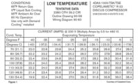
In these cases, the service technician must obtain compressor performance data from the compressor manufacturer. Many times, this data can be found on the Internet at the appropriate compressor manufacturer’s website, which can include compressor data in table form as shown in Figure 1. In that form, it can be seen that the amperage drawn by the compressor depends on both the condensing and evaporating temperature. This type of data also comes in curve form. It is often referred to as a rating chart or performance data for a particular compressor. Compressor manufacturers publish a rating or performance chart for each compressor they manufacture. Here is a field problem in which such a chart comes in handy.
Let’s assume the HCFC-22 compressor is operating at 230 volts and has an evaporator temperature of -15o°F and a condensing temperature of 1,00o°. Determine the correct current (amp) draw for this compressor using the table.
Solution: Using the current (amperage) table, the intersection of the 1,00o° condensing temperature with a -15o evaporating temperature results in an amp draw of 29.4 amps. This data tells us that this compressor operating under these pressures should draw close to 29.4 amps at 230 volts. The allowable tolerance is +/-10 percent. If the compressor was operating at 460 volts, the amperage values in the table would have to be multiplied by ½. Remember, the compressor must be operating at the proper voltage for the table to be meaningful.
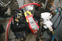
If the service technician now actually measures the compressor amps with an ammeter at the compressor and finds the amps to be very close to 29.4 amps, he has a pretty good idea that the compressor is up to specifications. If, however, the technician measures the current draw of the compressor and finds that it is pulling only 13 amps at these same conditions, there is a problem somewhere. Below is a list of causes why a compressor may draw low amperage:
• Bad suction and/or discharge valve;
• Starved evaporator;
• Worn rings;
• Leaking head gasket or valve plate gasket;
• Restricted liquid line or filter drier;
• Undercharged system;
• Weak motor;
• Metering device starving evaporator.
The service technician must now systematically check each of the above causes and find the one that is the cause for the low amp draw. Amperage tables like the one used in this example are invaluable tools in systematically troubleshooting and diagnosing compressor problems. As the condensing temperature decreases, so do the amperage. This is assuming a constant evaporating temperature.
Also, as the evaporating temperature decreases, so does the amperage. This is assuming a constant condensing pressure. Decreased condensing temperatures mean lower condensing pressures and a lower compression ratio. The compressor’s piston now operates with less pressure against it as it compresses the suction gases. This, in turn, is less stress on the motor and less amperage draws. Also, as the evaporating temperature decreases, so does the evaporating pressures. These lower pressures entering the compressor’s cylinders mean less dense vapors filling the cylinders. Less mass flow rate of refrigerant vapor is pumped by the compressor. This causes a decreased amp draw.
Note: Other operating conditions other than just evaporating and condensing temperatures (pressures) are used for these tables. The conditions in the upper left hand corner of data chart for our example must be met for the values to be 100 percent accurate. The conditions are:
• 65°F return gas temperature;
• 0° liquid subcooling;
• 95° ambient air over the condenser;
• 60 Hz operation.
If these conditions do not exist, the table will not be 100 percent accurate. However, for purposes of systematic field troubleshooting, these inaccuracies are not great enough to have any great effect on a good service technician’s judgment.
The point is, when troubleshooting a refrigeration or air conditioning compressor’s motor, the RLA or FLA value should not be used to determine if the compressor is good or bad, or if it is drawing the correct amps. Compressor performance data for a specific compressor must be used. If the RLA or FLA has any value to a refrigeration or air conditioning service technician, it is simply to determine at what amperage draw the compressor motor’s overload protector will open. RLA is also used to size wires, fuses, and contactors for the compressor.
Remember, the nameplate RLA does not change as the compressor motor load changes with temperatures and pressures. Again, the RLA should not be used by the refrigeration or air conditioning service technician to determine the proper refrigerant charge, or to determine if the compressor is running properly.
In summary, never compare or check the compressor’s actual amp draw against the nameplate RLA or FLA stamped on the compressor to determine if it is operating properly. Always refer to compressor performance or rating data for that compressor from the compressor manufacturer.
Publication date:03/07/2011


