In today’s competitive service market, every conscientious service technician should understand why a refrigeration or air conditioning system must have the proper amount of liquid subcooling. The amount of liquid subcooling not only affects system capacity, but also the effectiveness and capacity of expansion type metering devices.
Subcooling is defined as the difference between the measured liquid temperature and the liquid saturation temperature at a given pressure, or any sensible heat taken away from the 100 percent.
The saturated liquid point in the condenser can be defined as liquid subcooling. Liquid subcooling may occur from the start of the 100 percent saturated liquid point in the condenser to the metering device. The saturated liquid temperature can be obtained from a pressure/temperature relationship chart using the condensing pressure. This means that as soon as all of the saturated vapor in the condenser changes phase to saturated liquid, subcooling will start to occur if any more heat is taken away. Remember, this is now a temperature change or sensible heat change. So, any drop in temperature of the liquid below the saturation temperature for the pressure at that point will be considered liquid subcooling. There are two subcooling categories: condenser subcooling and total subcooling.
Condenser Subcooling
Condenser subcooling is the liquid subcooling present at the condenser’s bottom. It can be measured by subtracting the actual condenser liquid out temperature from the saturation temperature measured at the condenser outlet.
The formula is condensing temperature (saturated) minus condenser’s liquid out temperature equals condenser subcooling.
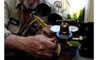
When subcooled, the refrigerant is not generating or losing any vapor pressure so there is no pressure/temperature relationship, and a pressure/temperature chart cannot be used. Thus, the condenser outlet temperature has to be measured with either a thermistor or thermocouple fastened to the condenser outlet (Figure 1). The saturated temperature, on the other hand, can be acquired from the condensing pressure read from a gauge on the condenser outlet. This is because a pressure/temperature relationship does exist in a saturated condition. If pressure drops exist in the system, the pressure must be measured where the temperature was taken to get an accurate liquid subcooling amount.
Here is an example: What would be the condenser subcooling if the head pressure on an R‑22 system was 211 psig and a thermistor at the condenser outlet measured 95˚F? (Assume no pressure drops through the condenser.)
Note that thermistors or thermocouples must have good thermal contact onto the refrigerant line. The line must be straight and lightly sanded to ensure good thermal contact. Insulation must be placed around the line to insulate against any outside ambient heat losses or gains.
To find the answer, convert 211 psig pressure (R‑22) to a 105˚ condensing temperature using a pressure/temperature chart.
105˚ (condensing saturation temperature) minus 95˚ (condenser out temperature) equals 10˚ (condenser subcooling).
This means that there is 10˚ of liquid subcooling leaving the condenser to feed the liquid line or receiver, depending on the type of system employed.
Now, in the next example, we will incorporate pressure drop through the condenser into the equation for condenser subcooling. In this case, the pressure will have to be measured where the condenser outlet temperature is taken.
So, what would be the condenser subcooling if the head pressure on an R‑22 system was 211 psig and a thermistor at the condenser outlet measured 95˚F, and the pressure read 205 psig at that point? Notice the 6 psi pressure drop through the condenser from line losses. The condenser outlet pressure can be read at the king valve, receiver charging valve, or simply by installing a line tap valve.
To find the answer, convert 205 psig R-22 (pressure) to 103˚ using a P/T chart.
So, 103˚ (saturation temperature at condenser outlet) minus 95˚ (condenser outlet temperature) equals 8˚ (condenser subcooling).
Total Subcooling
Total subcooling encompasses liquid subcooling from the 100 percent saturated liquid point in the condenser to the expansion valve or metering device. Figure 2 shows the thermistor insulated from the surrounding ambient. This means that total subcooling includes condenser subcooling and any subcooling that takes place after the condenser. Liquid can lose heat and subcool in the receiver, filter drier, and liquid line before it gets to the metering device. However, if there is any refrigerant vapor in the receiver, the subcooled liquid will not subcool further. The vapor will recondense to a liquid in the receiver. Both the liquid and the vapor will reach a new saturation temperature. As the vapor recondenses, it rejects heat, which will be absorbed by the subcooled liquid. Subcooling can be lost in this situation if the liquid stays in the receiver too long.
Total subcooling can be calculated by subtracting the liquid line temperature at the entrance of the metering device from the saturation temperature at that point. If there is pressure drop with the liquid travel, the concept of total subcooling is meaningless without incorporating pressure drops into the equation. The following example walks through a total subcooling calculation when pressure drop is not taken into consideration.
The formula involves a total subcooling calculation: Saturation temperature from pressure at a thermostatic expansion valve (TXV) inlet minus TXV inlet temperature equals total subcooling.
Here is an example: What would be the total subcooling if the head pressure of an R‑22 system was 223 psig and a thermistor on the liquid line at the entrance of the metering device read 90˚ (see Figure 2) assuming no pressure drop?
For the answer, convert 223 psig (R‑22) to a 109˚ condensing temperature using a pressure/temperature chart.
So, 109˚ (condensing saturation temperature) minus 90° (liquid at metering device temperature) equals 19° (total subcooling). This means that there is 19° of total liquid subcooling before the liquid enters the metering device.
When measuring the liquid line temperature at the entrance of a TXV or automatic expansion valve (AXV) metering device, place the thermistor or thermocouple on the liquid line about 3‑4 inches in front of the expansion valve and insulate it from ambient heat gains (Figure 2). Measurement instruments placed too close to the metering device will measure colder temperatures due to heat conduction to the colder expansion device.
Pressure Drop
In the next example, we will incorporate pressure drop into the system as the liquid travels through the condenser and to the metering device. This is typical of most medium- and large-size systems.
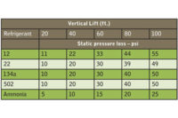
For example, what would be the total subcooling if the head pressure of an R-22 system was 223 psig and a thermistor on the liquid line at the entrance of the metering device read 90˚, and the pressure was 216 psig at that point? Notice the 7 psi pressure drop on the liquid before it reached the metering device. This pressure drop could be static, friction, or both. The pressure of the liquid has to be measured just before the metering device where the 90° temperature was taken. Line tap valves are often needed for this procedure.
To find the answer, convert 216 psig (R-22) to a 107˚ saturated temperature using a pressure/temperature chart. So, 107˚ (saturated temperature for pressure 216 psig at TXV inlet) minus 90˚ (liquid at metering device temperature) minus 17 (total subcooling).
Publication date: 02/6/2012


