 Today, compressor overheating is one of the HVACR industry’s most serious field problems. Compressor overheating is usually caused from high compression ratios. High compression ratios can be caused from a combination of high condensing pressures (temperatures) and low suction (evaporating) pressures.
Here are some of the causes for high condensing temperatures:
• Dirty condenser coils;
• Restricted condenser airflow (fan out);
• Air/noncondensable in the system;
• Overcharged system;
• High ambient temperature; and
• Recirculated condenser air.
Now, here are some causes for low suction pressures:
• Iced evaporator coils;
• Restricted evaporator airflow (fan out);
• Undercharged system;
• Dirty evaporator coil;
• End of the running cycle;
• Thermostat or LPC set wrong;
• Low evaporator heat load; and
• Defrost clock or heater malfunction.
Voltage Unbalance
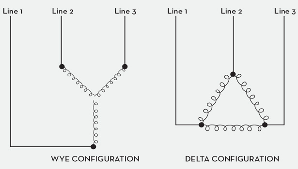
While one of the more elusive causes of compressor motor overheating and failure is voltage unbalance, this column will address voltage unbalance in three-phase compressor motors. Voltage unbalance can be found with a voltmeter by measuring between phases on the compressor’s motor terminals, at the disconnect, or at the contactor or starter terminals. Some of the more common configurations in three-phase motor windings are the Wye and Delta configurations.
By simply measuring voltages between line 1 to line 2, line 2 to line 3, and line 3 to line 1 — and performing a few simple mathematical calculations — a wise technician can determine if there is a voltage unbalance problem.
Voltage unbalances exceeding more than 2 percent in three-phase systems can cause current unbalance among the windings. These voltage and current unbalances can cause an increase in winding temperature and an overheating problem that can be detrimental to the motor. Three-phase motor terminals are connected directly to the motor windings. Motor windings are housed in the motor barrel. The motor barrel houses, protects, and cools the motor windings as superheated refrigerant gas flows through the motor barrel.
Measuring Voltage Unbalance
Now let’s look at an example of how to measure voltage imbalance.
Step 1
Measure line voltage between phases. Here are three readings:
line 1 to line 2 = 216 V
line 2 to line 3 = 223 V
line 3 to line 1 = 225 V
Step 2
Average the three line voltage readings.
216 V + 223 V + 225 V = 664 V
664 V ÷ 3 = 221.33 average V
Step 3
Find the unbalance for each phase by figuring the difference between each phase voltage (Step 1) and the average volts (Step 2). Note: Make sure the subtraction comes out to be a positive number.
line 1 to line 2 = 221.33–216 = 5.33 V
line 2 to line 3 = 223–221.33 = 1.67 V
line 1 to line 3 = 225–221.33 = 3.67 V
Step 4
Take the largest unbalance in Step 3, which in this case is 5.33 V, and divide it by the average found in Step 2. Multiplying by 100 puts it in a percentage form.
Here is the equation for the information noted previously.
Percentage Unbalance = (largest unbalance ÷ average volts) x 100.
Percentage Unbalance = (5.33 ÷ 221.33) x 100.
Percentage Unbalance = 2.4 percent.
As mentioned earlier, a voltage unbalance exceeding more than 2 percent in three-phase systems can cause excessive current unbalance among the windings. This above calculated voltage unbalance of 2.4 percent exceeds the 2 percent limit, and can cause an increase in winding temperature that is detrimental to the motor. In fact, this equation governs how voltage unbalance affects the temperature rise in the motor.
Percentage Temperature Rise = 2 x (percent voltage unbalanced) 2
Percentage Temperature Rise = 2 x (2.4)2
Percentage Temperature Rise = 11.52 percent
This equation shows that the voltage unbalance of 2.4 percent caused an 11.52 percent increase in winding temperature over the motor’s normal operating winding temperature. The building owner and local power company should be notified of the unbalance problem.
Publication date: 5/6/2013
Want more HVAC industry news and information? Join The NEWS on Facebook, Twitter, and LinkedIn today!


