The air duct calculator, or “ductulator,” is a commonly used tool for designing and installing duct systems. Unfortunately, many designers and technicians receive limited instructions on its correct use. This lack of instruction frequently results in duct systems that fail to perform as intended.
It’s typical to find that delivered airflow into a home is less than 65 percent of what’s required. In addition to low airflow, common problems include: excessive total external static pressure (TESP), ongoing equipment problems, nagging discomfort, thermostat wars, costly callbacks, and increased warranty costs. Let’s look at how four incorrect uses of an air duct calculator can contribute to these problems.
NO. 1 — THE .10 FRICTION RATE
Consistently using the .10 friction rate to design a duct system tops the list of incorrect duct calculator uses. One reason it is so widespread is due to the recommended residential setting found on so many of them. This value is usually found in the center of the calculator, which is why so many people believe it’s the design number to use.
To put the friction rate number in context, the recommended residential setting on the duct calculator is based on 100 effective feet of duct — not actual length. Effective feet is a combination of actual duct length and the equivalent duct length of each fitting. The equivalent length is often forgotten and can have a huge impact on design and performance.
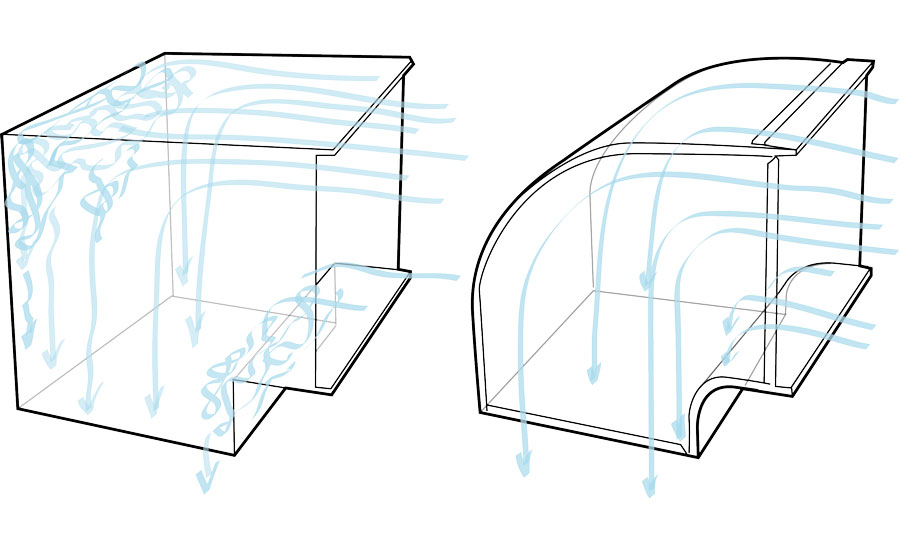
Equivalent length compares a duct fitting to what its length would be if it were straight. Every duct fitting and connection you use has an associated equivalent length. Duct fittings with sharp turns have higher equivalent lengths than fittings with gradual, smooth turns.
Examples of how quickly equivalent length adds up are available by looking at the back of some duct calculators. There, you’ll find various groups of duct fittings and their corresponding equivalent lengths.
For example, a 90-degree elbow with a square throat, round heel, and no turning vanes that is 24 inches wide has an equivalent length of 100 feet of straight duct. If you size your duct system at a .10 friction rate, this one duct fitting will use all the pressure allowed for the entire system — there’s nothing left for the remainder of the duct system.
Using a curved throat or turning vanes on the same sized elbow lowers equivalent length to 20 feet of straight duct. That’s a pretty big reduction from such a small change. So, remember to keep equivalent lengths low by using fittings that allow for smooth airflow through the system.
NO. 2 — SIZING FLEXIBLE DUCTS
Unless it’s stated on the front of the duct calculator that it is specifically for use with flexible ducts, it’s probably intended for use with sheet metal. When you size flexible ducts with a sheet metal duct calculator, low airflow and high static pressure are sure to follow.
These materials are two completely different surfaces. Sheet metal is smooth, and flex is an uneven helix core. Flex offers more resistance to airflow because of its spiraled surface, and it isn’t accounted for on a sheet metal duct calculator. So, it’s necessary to use a flexible duct calculator if you install flexible duct.
Most distributors and flexible duct manufacturers offer them and would love it if you had one. Make a point to switch to the proper duct calculator, and enlarge your ducts to increase the chances for a properly operating system.
NO. 3 — NOT ALLOWING FOR INTERNAL DUCT LINERS
While this may seem like common sense, it’s easy to forget duct sizes should be based on internal duct dimensions, not external. It’s amazing how frequently we encounter this in the field. If overlooked, you could end up with an internal area much smaller than intended, especially if the duct liner is thick.
A simple test to determine liner thickness is to install a test port in the duct, then use a static pressure tip as a depth gauge. Insert the static pressure tip into the test port, and pull back until you feel the curved end of the static pressure tip compress the liner.
Measure the distance between the duct wall and the magnet of the pressure tip. Remove the static pressure tip, and then measure from the inside of the curved tip to the magnet. Subtract the two measurements to determine duct liner thickness.
NO. 4 — MEASURING AIRFLOW
The last way a duct calculator is used incorrectly is to measure airflow. At first glance, the test sounds like a great way to determine airflow, but it fails to consider some basic principles.
Technicians using this method are taught to take a single static pressure measurement in the duct system and line it up with the corresponding duct size on the calculator. They then interpret the intersection of the duct size and friction rate pressure as airflow through the duct.
For example, let’s say a technician measures a static pressure of .06 inches of water column (w.c) in a 24-by-10 plain metal duct. They then pull out their duct calculator and set the duct size to 24-by-10. Next, they locate the static pressure measurement on the friction rate per 100 feet of duct line. They interpret the point where the lines intersect as airflow through the duct. In this case, that is 1200 cfm.
Now that I’ve briefly explained how it’s done, I advise you to never use the air duct calculator this way. It isn’t a measurement tool. The air duct calculator is for design only.
To determine airflow in a duct by pressure, you need to measure velocity pressure, not static pressure. Velocity pressure is measured with a Pitot tube at multiple points in the duct using a traverse procedure, which is converted to air velocity. Fortunately, most test instruments perform this conversion for you as you measure.
Once multiple velocity readings have been taken and averaged, they are plugged into the airflow formula:
cfm = velocity x area (in square feet). Static pressure and a duct calculator can’t determine these values.
BRINGING IT TOGETHER
To better understand the foundational principles behind a duct calculator, start by thoroughly studying ACCA Manual D — the industry standard for duct design. This text provides insight on the application and original context of this valuable tool and will keep you from incorrectly using it the ways I’ve described above.
As you learn the principles, pay attention to equipment and system details, such as fan capacity, coil pressure drop, filter size, and duct fitting choices. These components play a crucial role in system design and can’t be forgotten.
Don’t forget to measure TESP and airflow to verify your designs work as intended — this is where the rubber meets the road. You’ll find field measurements reveal the hidden truth about whether a system is sized correctly with an air duct calculator or not.


