Our industry uses ranges like 350 to 400 cfm (cubic feet per minute) per ton to estimate required cooling and heat pump airflow. With a few pieces of information, you can use similar ranges for gas furnaces to estimate heating airflow.
Instead of relying on temperature rise to assume you have the right airflow, you can determine airflow requirements upfront. Let’s look at how you can estimate gas heating airflow in four simple steps.
Step One: Gather Nameplate Information
Before you can estimate heating airflow, you need to determine the furnace type. Is it a natural draft (70 percent), fan-assisted (80 percent+), or condensing (90 percent+) furnace? Next, look at the furnace nameplate. You’ll need three pieces of information from it for heating airflow calculations. They are:
- Rated Btu/hr (British thermal units per hour) input capacity
- Model number (to determine fan-rated tonnage and the correct fan table to use)
- Maximum-rated TESP (total external static pressure).
You need the furnace type and rated Btu input capacity to estimate required heating airflow. The model number and maximum-rated TESP come into play in the fourth step where you measure static pressure and compare required airflow (what you need) to plotted fan airflow (what you have).

Click chart to enlarge
You’ll need to gather three pieces of furnace nameplate information to estimate heating airflow. Each nameplate is a little different.
Step Two: Visual Inspection
While gathering furnace nameplate information, it’s a good idea to remove the blower compartment door and perform a visual inspection. Locate the blower speed settings for the furnace and record them for future use.
If the furnace has a PSC (permanent split capacitor) blower motor, determine the heating speed taps used on the circuit board or fan relay. Single-stage furnaces are the easiest; they use one heating speed. Two-stage furnaces use two blower speeds for low-heat and high-heat.
If the furnace has an ECM (electronically commutated motor) blower assembly, you’ll need the manufacturer’s equipment installation manual or specifications. Use information in these documents to interpret dip switch settings on the control board or determine airflow settings from the controller of a communicating system.
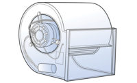
Once you have your blower speed settings, inspect the blower wheel vanes to assure they’re clean and undamaged. If the vanes are compacted with dirt, airflow drops substantially. It’s estimated an 1/8-inch coating of dust on a blower wheel reduces fan airflow as much as 30 percent.
Clean the blower wheel if it’s dirty. If you’re testing a condensing furnace, also look at the secondary heat exchanger while the blower assembly is out. If the blower is dirty, chances are high the secondary heat exchanger is too. Now is the perfect time to take care of it.
Step Three: Estimate Heating Airflow
Required heating airflow is determined per 10,000 Btu of rated furnace input. Think of this like cfm per ton for cooling operation. To estimate heating airflow, take the furnace rated Btu input and divide by 10,000. Next, multiply this number by the following airflow factors based on each furnace type.
- Natural Draft Furnaces (70 percent): 100 cfm per 10,000 rated Btu input
- Fan-Assisted Furnaces (80 percent+): 130 cfm per 10,000 rated Btu input
- Condensing Furnaces (90 percent+): 150 cfm per 10,000 rated Btu input
Example: You are dispatched to service a condensing furnace and want to know how much airflow it needs. You look at the furnace nameplate and see the furnace’s rated input is 60,000 Btu. Divide 60,000 by 10,000 to get the result (60,000 ÷ 10,000 = 6).
Since this is a condensing furnace, you know it needs 150 cfm per 10,000 Btu rated input. You multiply six times 150 cfm (150 x 6 cfm) to see this furnace needs approximately 900 cfm of airflow moving across the heat exchanger.
Step Four: Compare Estimated to Plotted
Once you know your estimated heating airflow, you can turn the furnace on and measure TESP to plot fan airflow on the furnace’s fan table. You can compare the amount of airflow you need to what you have.
To measure TESP on a gas furnace, you’ll need to install test ports where air enters and exits the equipment and then measure pressures at each location. Once you have the readings, add the two pressure readings together to determine measured TESP and record the reading.
Next, locate the furnace’s fan table. It’s usually located in the installation instructions. Find the appropriate fan table that matches your furnace’s model number. On the fan table, locate the heating fan speed in use and lightly circle it.
Next, find the column that is closest to your measured TESP and lightly circle it. You should have two points circled on the fan table at this point.
Use a straight edge and line up your measured TESP and the fan speed. The point where they intersect indicates how much air the fan is moving. Record the airflow so you can compare it to your required heating airflow. A properly operating fan should deliver +/- 10 percent of required airflow near the equipment’s maximum-rated TESP that you found on the nameplate.
In the previous example, you needed 900 cfm for the 60,000 Btu input condensing furnace you’re testing. Let’s say your plotted fan airflow is 600 cfm. If you compare this to your required heating airflow, you’re only moving 67 percent of what you need (600 cfm ÷ 900 cfm= 67% percent).
A furnace only moving 67 percent of its required airflow needs your help. Don’t be surprised if the primary limit switch is cycling and the heat exchanger has been overheating.
Next Steps
As you begin to test and compare airflow readings, you may discover you need the same amount of airflow for cooling and heating. While this might seem like a lot of steps, it is much more intimidating on paper than it is to do it. With a little practice, you can perform these steps in less than five minutes.
Now it’s your turn. Check heating airflow on your next call and see how close you are. I think you’ll be surprised at the amount of airflow issues you discover. Additional testing helps pinpoint whether it’s an issue with the coil, filter, or duct system.
Once you have airflow testing down, add equipment temperatures to your airflow readings. You can plug them into the sensible heat formula (cfm x ∆t x 1.08) to see how close the furnace is to delivering its rated Btu output. It will open your eyes to another level of diagnostics and the opportunity to better serve your customers.


