
Most residential HVAC contractors and technicians want to do a great job for their customers. Nothing feels better than figuring out the cause of a homeowner’s issue and then implementing the right solution.
However, solving issues and meeting customer expectations can be a real challenge. The root cause of issues may be hard to determine, and even if it can be identified, the right solution may be more involved than simply replacing the equipment. Convincing the homeowner to move forward with your solution can be especially challenging if they have a quote from a competitor company that offers a less expensive, but ultimately inferior “solution.” The key to differentiating yourself and selling the right solution is having the data to credibly explain issues and the confidence to solve problems — and in many cases, that includes a good understanding the system airflow and pressures.
Why Airflow Measurement Matters
If you work in the HVAC industry, it makes sense that you need to know how air flows in ducts and what factors affect the flow.
To optimize a new or existing HVAC cooling system, you need to ensure the entire air delivery system — including the ductwork — is in good condition, and the system does the right amount of work to control both the temperature (sensible cooling) and humidity (latent cooling).
The sensible and latent capacity of a system depends on airflow, and if the airflow is too high or too low, you can run into comfort and efficiency issues that impact the homeowner. However, setting the system airflow in the right zone is more difficult than it might initially seem. A recent study of 107 residential air conditioning systems found that only 41% of systems had airflow in the target range for the climate zone (in this study, 300-400 cfm per ton of cooling). The same study showed that ECM motors did not significantly improve the situation, with only 50% of systems with ECM motors in the target flow range.
We are going to use a general rule of thumb for target flow ranges based on the climate type, as shown in Table 1; however, defining a target air flow rate depends on multiple factors. The equipment manufacturer’s extended performance data will provide the unit’s sensible and latent capacity at various conditions. The HVAC designer’s job is to ensure the system is properly sized to both cool the home and provide the right amount of dehumidification, given load expectations. You can find a more detailed discussion on this topic at www.hvacairflow.com.
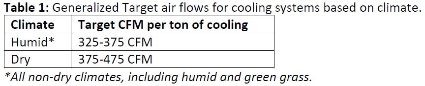
Click table to enlarge
Low Airflow: High Energy Bills, Frozen Coil, Poor Performance
Airflow that is too low is probably more common than airflow that is too high, and it reduces the system’s capacity for sensible cooling. With reduced capacity, a properly sized air conditioner may not maintain the set point on days that are near the design temperature, despite running nonstop. This means the homeowner hears the a/c running all day but is still uncomfortable. This reduced-capacity problem contributes to a related problem: oversizing the air conditioning system.
In extreme cases, low airflow leads to the evaporator coil temperature dropping to the point where condensation begins to freeze. This is especially true if the refrigerant charge is low. A frozen coil eventually blocks almost all the airflow, and the system stops cooling altogether.
Low airflow can also lead to liquid slugging. If there is not enough air passing over the evaporator coil, all of the refrigerant will not evaporate before it reaches the end of the coil, and some of it will begin to return back to the compressor as liquid. Coils are designed for incoming refrigerant gas, and if it is in the liquid state, it can damage the compressor.
High Airflow Can Create “The Cave”
The biggest problem with high airflow is insufficient dehumidification. As airflow increases, air has less dwell time as it passes across the coil and does not cool as much. Consequently, there is less opportunity for moisture to condense on the cold surface of the coil. This means the humidity in the house will be higher than it should be.
Most guidelines recommend keeping the indoor relative humidity below 50%. When humidity is higher, homeowners may complain that it is not comfortable, even when the thermostat set point is perfectly maintained. “It’s a cave” is the way one trainer describes it. Even though it’s cool inside, the high humidity feels like you’re in a cave with water seeping through the cracks all around you.
High indoor humidity can also cause condensation on indoor surfaces or ductwork, and these wet surfaces can lead to mold growth and poor indoor air quality. Lack of comfort because of high humidity often leads homeowners to set the temperature lower on the thermostat. But a cooler indoor temperature makes the risk of condensation and mold growth even higher. It is a vicious cycle.
HVAC contractors who know how to set airflow to achieve proper indoor humidity tell how homeowners react to having relative indoor humidity below 50% when they may have been dealing with indoor humidity over 60% for years. At first, the homeowner may complain that it is too cold when they set the thermostat at 71°F, like they always have. Then the contractor will explain that with the proper indoor humidity, they no longer need to set it so cool to be comfortable. They will often be comfortable with a set point several degrees higher, and the lower utility bills will make them more “comfortable” as well.
Other causes of high indoor humidity include oversized, short-cycling equipment and duct leakage, but getting the proper system airflow is a great start.
Beyond the “Handometer” — Options for Measuring Air Flow
We are going to give you a brief overview of the 10 most common methods to measure HVAC airflow. Be warned, if you ask five experts what they think on this topic, you will probably get five different answers. So, while this may not be the “final word,” it will give you an idea of what your options are and help you make an informed decision. You can have a significant impact on your business by moving beyond the “handometer” for measuring air flow. It will improve how you understand and solve issues and differentiate yourself.
Here are four items to consider as you decide which method(s) you will use:
1. Accuracy
You need “good accuracy” — but in many cases, it does not need to be super accurate. Something on the order of +/- 10% or better. With this type of reading, you will be able to make a good analysis and sell the right solution with confidence. However, you need to always get readings in this range so that you have confidence that the measurement is right. This leads to item 2.
2. Consistency of Measurements
What do we mean by consistency? Think about it this way: If you sent five technicians out to the same house and asked each to measure the system airflow using their current preferred method, how confident would you be that all five come back with the same flow measurement within +/- 10%? What happens if they all have less than a year of experience? You want to pick a method that delivers consistent readings — no matter which system you are measuring, how old or dirty the system is, and no matter who is making the measurement.
3. Time Required
No one gets to the end of the day and thinks “I had plenty of time today to get everything done.” So, as you consider the various methods, the time it takes should be included — not only to make the measurement but how much might it take if you are not sure of the reading.
4. Tool Cost
This one is obvious. You need to know what tools are needed and how much it’s going to cost. Some methods can be done with a very limited investment, while others can run nearly $3,000.
These are related: Measurements that are more cost-effective typically require more time and experience and may not deliver consistency across different levels of expertise. To us, the most important consideration is confidence in the airflow reading. If you have a consistent measurement you trust that is “good enough” accuracy, you will be able to change your approach and sell better solutions on a day-in, day-out basis.
Table 2 below outlines these key considerations for the most common approaches. The first four methods are approaches recognized in the new ACCA-310 standard (June 2020) focused on grading HVAC installations. Many other methods are also used in residential HVAC — generally lower accuracy with lower confidence in residential settings, but they can be used successfully if the technician is well-trained, has the right information, and (in the case of traverse) if the installation has proper straight runs.
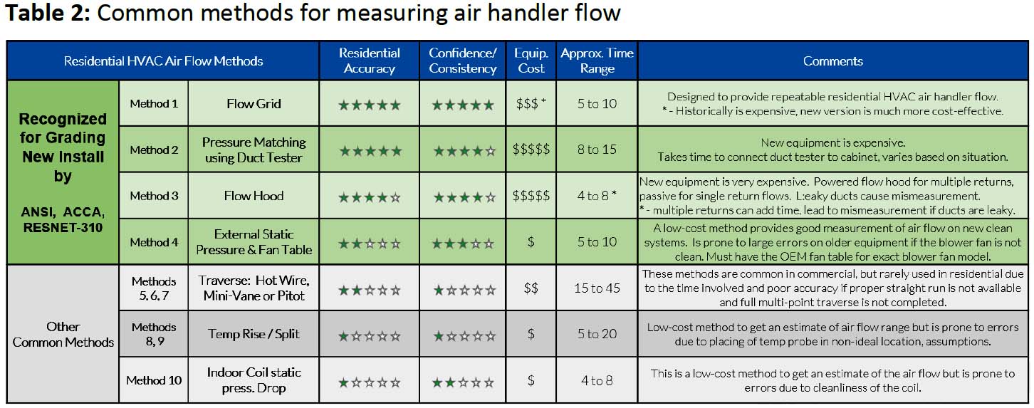
Click table to enlarge

This is a patented design from TEC (The Energy Conservatory) created specifically to measure residential HVAC total system air flow. It delivers consistent and accurate results across multiple situations and expertise levels and is not impacted by age or condition of the equipment. It also comes with the TrueFlow App, which supports two workflows — measuring flow only or a workflow which includes a series of static pressure measurements for analysis of what might be causing flow conditions. Historically, the drawback of this approach was the cost, but the newest version is much more cost-effective.
Conclusion: This is a very accurate and repeatable approach to measuring air handler flow, made more cost-effective with the new release of the Digital TrueFlow.

This approach provides good accuracy and delivers consistent results, especially when connected directly to the blower fan cabinet. This equipment is very expensive if used only for flow measurement but has the added benefit of doing both duct leakage and airflow. It requires blocking off the return duct for systems with multiple returns and can be time-consuming to hook up to blower cabinet. You also need to ensure the equipment’s fan can match the blower fan airflow rate, as they are designed for measuring duct leakage, not total system airflow.
Conclusion: This is an accurate but time-consuming approach to measure airflow, since product is designed to measure duct leakage — but a nice option if you already have the equipment.
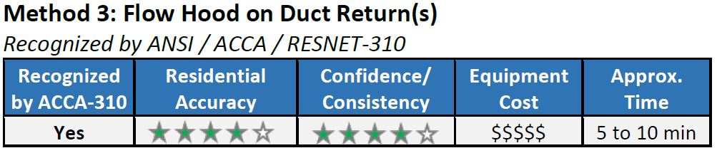
This approach is easy to use and provides good accuracy if used on returns with low leakage. You will need to look at how many returns there are to ensure the flow hood you are using has the right flow range. If you have a single return, you will likely need a passive flow hood (bolometer) to be able to read high enough. If you have multiple returns, you will add up individual flows but will likely need a powered flow hood to read low enough. Like duct leakage test equipment, this equipment is also very expensive but is designed for more than one purpose, as a powered flow hood can also be used to measure register supply flows in rooms as part of air balancing.
Conclusion: Expensive but easy to use and provides good measurement if used properly on returns with low leakage. May need both a powered and passive hood to cover full range.

This is one of the most common approaches to estimate air flow rates, and can be accurate if the condition and installation of the equipment matches what the manufacturer tested when making the tables. It involves measuring the static pressure from the entrance and exit of equipment containing the blower fan. There are some common challenges to this method, and the first is that you must have the specific OEM fan table to convert external static pressure to flow for the equipment you are measuring. Second is to get the condition to match the table, as dirty blower wheels and dirty heat exchanger fins restrict the air flow and significantly change the relationship between pressure and flow which is given in the table. Last is to confirm and make any adjustments if the orientation of the inlet to the blower is different than specified in the table.
Conclusion: Cost-effective method for estimating air flow. Can be effective on a new installations but is prone to large errors on older equipment if the system is not clean and in good condition like that specified in the OEM tables.

A traverse measurement involves gathering airflow data from different points in a duct and combining them to calculate the air flow. Two standards are commonly used for the procedure — ASHRAE Standard 111 and ISO 3966. The traverse is typically done with one of three devices: a pitot-static tube, a mini-vane anemometer, or a hot-wire anemometer. Each are relatively cost-effective and good at measuring velocity at a single point; however, to arrive at the average cfm per volumetric flow, you need to measure many different points and then make calculations. This can be time-consuming and complex to do. The other challenge is finding a straight run that is long enough for an accurate measurement, which can rarely be found in residential systems.
Conclusion: These methods are common in commercial settings, but rarely used in residential applications due to the time involved and poor accuracy if proper straight run is not available.

Measuring the temperature change from the supply and return ducts is a very cost-effective and can be a quick method to estimate flow. However, for measuring flow, it can be more problematic. Readings are dependent on probe location, especially in the supply duct, and can easily be misinterpreted by the inexperienced. You also will be looking up conversion from temperature to flow in tables and will need to ensure various assumptions and conditions match.
Conclusion: Low-cost method to get a rough estimate of air flow. Prone to large errors due to measurement location, age of equipment, and assumptions needed.

Measuring the static pressure drop across the indoor coil faces similar challenges as measuring static pressure rise from the blower (TESP). You will need the original tables of static pressure drop versus airflow from the manufacturer. As before, remember that these values are for a clean coil. The other challenge with this approach is that the coil pressure drop tables typically include two different values for wet and dry conditions. Wetness and dryness usually aren’t defined but have a large effect on accuracy.
Conclusion: This is a low-cost method to get a sense of air flow range, but is prone to large errors due to age of equipment and coil conditions.
Improving System Airflow Measurement and Diagnosis Will Be an Industry Effort
Measuring HVAC total system airflow will enable technicians to better solve homeowner comfort and system performance issues, and we believe it is a key step in the evolution of our industry and represents an opportunity to differentiate for those who adopt a consistent approach. As an industry, we need manufacturers, service providers, and educational teams to come together to make it easier to accurately measure and diagnose air flow issues. We believe it will result in more consistently optimized systems, better homeowner comfort, and ultimately a better industry.
We have come together, along with Bill Spohn of TruTech Tools, to create a series of educational materials related to the measurement and diagnosis of HVAC total system air flow, including the methods outlined in this article. It can be found at www.hvacairflow.com.


