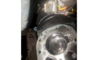
HVAC distributor cfm Distributors recently developed a list of items to test and/or questions to ask when dealing with sites that have experienced multiple failed compressors. The first step consists of determining the compressor’s mode of failure. Was it electrical or mechanical? This piece focuses on mechanical failures. Read our piece on electrical failures.
Airflow is one of the leading causes of failure for compressors. Most manufacturers recommend a nominal airflow of 400 cfm/ton. Enough airflow is needed to ensure adequate heat transfer to boil the refrigerant off in the evaporator so that the compressor does not become slugged with liquid.
After verifying airflow, the next step is looking at refrigerant charge. A low refrigerant charge means that the compressor motor won't be receiving the cooling necessary to keep its operating temperatures within a safe limit. Coupled with longer run times, lack of motor cooling will lead to compressor failure.
An excessive amount of refrigerant in the system can destroy the compressor through liquid slugging — the penetration of liquid refrigerant into moving parts of the compressor where only gaseous refrigerant was meant to go. Liquid slugging will quickly cause the compressor to fail.
The other two common causes of mechanical compressor failure are moisture contamination and low suction line velocity. When water mixes with lubricating oil, dangerous acids form and begin to corrode the compressor motor windings, causing what is known in the industry as an “acid burnout.” Most manufacturers recommend keeping the suction line velocity above 1,000 fpm. This ensures oil return back to the compressor.
In the event the compressor failure is occurring in a split system and it’s suspected that the cause of failure may be a result of line set application, technicians may need the distributor to run line set sizing calculations. To do that, technicians will need to provide a range of information: total line set length (the distance of pipe run from indoor to outdoor unit); the difference in elevation between the indoor and outdoor equipment and which piece of equipment is higher in elevation; and how many 90 elbows are installed, including both liquid and suction, as well as long or short radius. This is only elbows, not bends. Technicians should also mention any additional accessories that will be used in the refrigerant circuit.
If none of the above are prevalent, check these additional items:
- Is the AC unit operating in low ambient conditions? If so, does the unit have a dedicated low ambient head pressure controller and has it been configured properly?
- Does the unit have a crank case heater and is it working?
- Does the unit have a compressor blanket? These are sometimes used in conjunction with crank case heaters to help the compressor stay warm in compressor off-cycles and prevent the liquid refrigerant from settling to the sump of the compressor, causing the oil to float to the top and thus washing the oil out of the compressor when the compressor is energized.
- Does the unit have a freeze stat? If not, it might be advisable to install one on the suction line of the compressor.
- Is the anti-cycle set up in the stat? It could be short cycling due to an oversized system.
- Are there any “traps” present in the system? Systems utilizing R-410 refrigerant don’t require or recommend traps.
- Does the unit have the correct compressor?


