
The fan center’s purpose is to control when the indoor fan turns on. Before the integrated gas control board, the indoor fan on gas and oil furnaces would either turn on at the same times as the heat or with a time-delay relay. Fan centers came along as a way to separately turn on the fan without necessarily turning on the heat. This is why technicians will most likely run into fan centers on older furnaces where air conditioning was added later.
A fan center consists of a transformer with screw terminals which is solder connected to the coil of a relay, both of which are mounted together on a plate. It is not uncommon to find these on modern heat pumps, electric backup heat, and any application where the fan needs to use two stages or where various accessories need to turn on with the fan — or even a combination of both. Therefore, understanding the basics will go a long way for troubleshooting.
The Transformer and Relay
The transformer is typically a 120V primary and 24V secondary, but it’s not an ordinary transformer that technicians necessarily carry on their vans. The fan center transformer has RCWGY terminals designed for thermostat control wiring. The 24V secondary side is factory-connected to R and C, and C and G are factory-soldered into the coil of the relay. The relay plugs into a receptacle, making the relay field replaceable. The relay coil is usually 24V, and the relay is usually single-pole, double-throw (SPDT), meaning it has two sets of contacts — one normally closed and one normally open. If the fan only has one speed, the normally closed contacts will not be used.
If the fan does have two speeds, the low speed will be on the normally closed contacts and used for heating, while the high speed will be on the normally open contacts and used for cooling or constant fan. If the relay is only a single pole, single-throw (SPST), and the fan has two speeds, use only the high speed. In short, the high speed will always be on the normally open contacts. The relays that are double pole are used in applications to control auxiliary loads, such as electronic air cleaners and humidifiers. The transformer and relay receptacle are mounted on a 4x4 plate, which can be mounted on an outlet box sold separately to conceal the high voltage wires.
Installation Basics
The fan center will typically come with instructions that specify that the installer must be a trained, experienced service technician and that failure to follow instructions could damage the product or cause hazardous conditions. This warning should not be taken lightly, as there are many wrong ways to install a fan center, and it is highly recommended that the person installing it understands how the equipment works and how to safely handle electrical circuits.
Always disconnect line voltage power supply before removing wire nuts or making connections. When checking out operations after installation, be sure to operate the system for at least one complete cycle in heating and in cooling.
Figure 1 is a very basic wiring diagram for a single-speed furnace. The technician will notice that the primary side of the transformer is wired parallel to the indoor blower motor, and the limit and relay are in series with the motor. The “plenum switch,” also referred to as a “fan limit switch,” is not an included part but is often found in furnaces with fan centers. There are two switches inside the plenum switch device — one switch to cut the fan in and out when the plenum reaches certain temperatures, and a limit switch that can be wired to either cut power to the controls or cut power to the fan if the plenum gets too hot. The plenum switch consists of a bimetal helix that expands and contracts as its temperature changes, causing sets of contacts to make and break. The technician manually sets the cut-in, cut-out, and high-limit temperatures by adjusting pins on a dial. It is very important to push this dial in before moving the pins so as to not twist and damage the bimetal. Typical fan switch settings are 130-150° for “fan on,” 110-90° for “fan off,” and a typical limit setting would be 200°.

Figure 1: When the relay coil is energized on a call between G and C, it closes the set of normally open contacts which closes the 120V circuit to power the fan. (Courtesy of Lianna Schwalenberg)
Sequence of Operations
The thermostat is the switch that will close the circuit between the secondary side of the transformer to whatever is being called — heating, cooling, or the fan. With this basic setup, there are three ways the fan will turn on: 1) when the plenum reaches above a certain temperature, 2) on a call for cooling when the fan is in auto, or 3) when the fan is set to be on continuously. This is still the same practice for controlling the fan in modern furnaces, but it is done with more electronics such as timers in control boards.
When the relay coil is energized on a call between G and C, it closes the set of normally open contacts which closes the 120V circuit to power the fan. The fan will remain powered, as long as the limit switch is closed and the relay coil is energized. Another way the fan will turn on is if the plenum reaches above a certain temperature, and the fan switch will keep the fan powered until the switch senses the temperature drops below the cut-out point. This is how the fan turns on and off in heating — it is solely based on the temperature of the furnace. Yes, this control is old-school, but these furnaces are still out there.
The fan will turn off when the plenum cools off, gets too hot, or the fan center no longer receives a call for G.
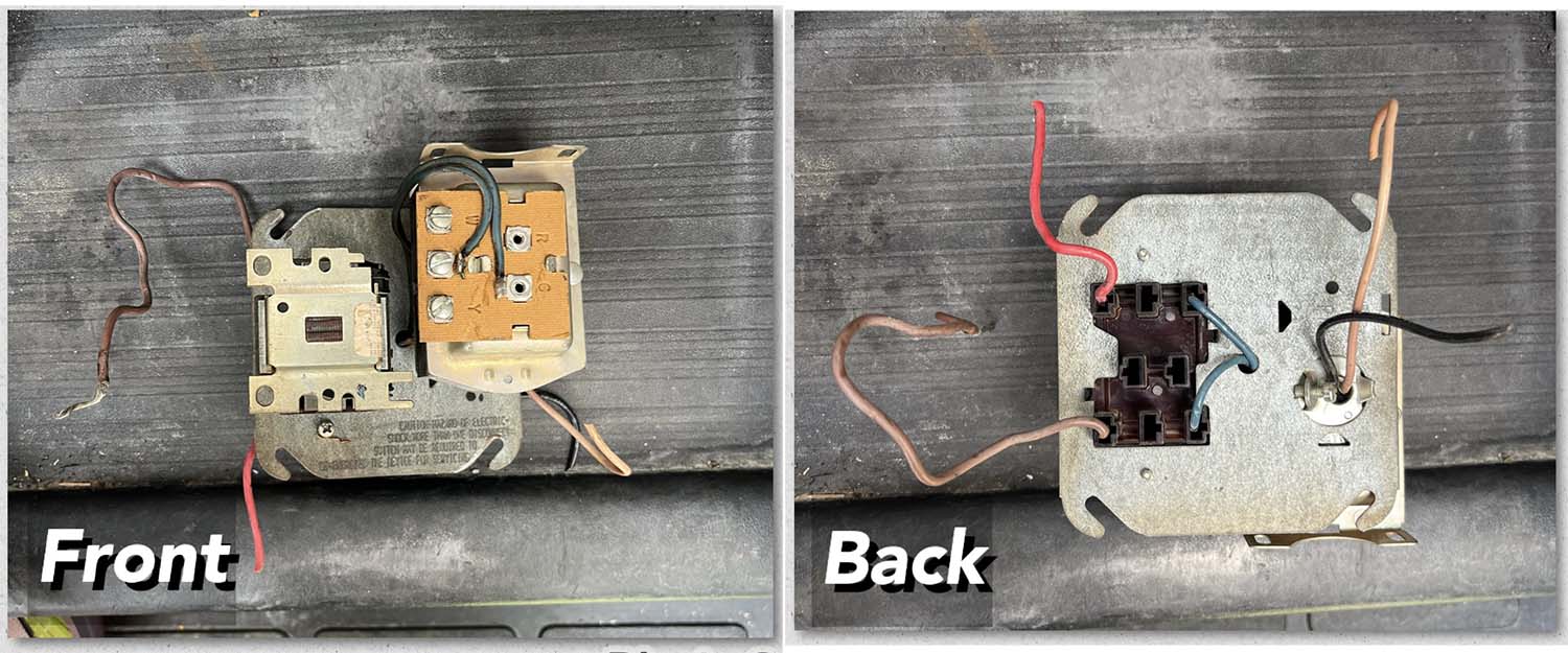
Figure 2: Front and back view of a fan center which, pictured here, consists of a 120V primary/24V secondary transformer and a relay on a plug receptacle. (Courtesy of Lianna Schwalenberg)
The K Company
Troubleshooting
Because the fan center only consists of two parts, troubleshooting is very simple — either the transformer has failed, or the relay has failed. The relay has failed if there is 24V measured across the coil and the contacts do not make. The relay coil could also be shorted where very little resistance is measured across the coil. As mentioned previously, the relay is field-replaceable, meaning the technician only needs to replace the relay and not necessarily the entire fan center. The transformer has failed if it has 120V measured supply into the primary and not 24V measured out, which can be checked at R and C on the transformer. If the transformer does not have a circuit breaker, any shorts in the circuit will permanently damage the transformer.
As with any component changeout, it is extremely important to pay attention to context clues. While transformers and relays can go bad, sometimes they are prematurely killed by a greater problem. Pay attention to all of the wires that are not being changed out and look for damages or shorts where metal is touching metal. Not all older furnaces have rollout switches to turn the unit off before a combustion issue causes damage. If heating is not needed, the technician can get the customer through the summer by disabling the call for heat.


