
Note: A thorough review of these last two articles will help in understanding the concept of voltage feedback covered in this article.
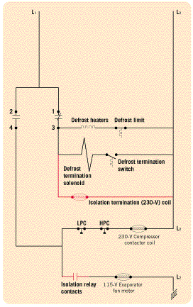
Figure 1 shows an electrical diagram of a typical commercial refrigeration system. The diagram includes:
Notice that all of the power-consuming devices (loads) in Figure 1 are 230 V. If some of these loads were changed to 115-V loads, problems could arise from voltage feedback.
Let’s say the evaporator fans are 115-V devices; the circuit in the defrost mode would have the contacts between 2 and 4 of the time clock being open, and defrost circuit contacts between 1 and 3 being closed.
Now let’s say there are now two power-consuming devices (loads) in series being fed voltage by line 2 (L2). The two loads in series are the 230-V compressor contactor coil (CC1) and the 115-V evaporator fan. Even though the contacts between 2 and 4 would be open, there is a feedback circuit from L2 through CC1, through the evaporator fans to neutral (ground) and back.
The feedback circuit has a complete path for current to flow because the current can alternate from line L2, through the compressor contactor coil and evaporator fan motor, to neutral (ground). This can happen at 60 cycles per sec (60 Hz).
Because CC1 and evaporator fan motor are in series with one another when in defrost, both power-consuming devices will see a lower voltage than they are rated for. The lowered voltage each will experience will depend on their individual impedance (ac resistance). CC1 will probably be humming and getting hot, and the evaporator fan may be running slowly.
Both loads will eventually burn out because the low-voltage condition creates a high-amperage condition. This situation is what is referred to as voltage feedback. The voltage from L2 is feeding both power-consuming devices when in defrost mode.
Voltage feedback often happens when power-consuming devices with different voltage magnitudes (230 and 115) are in the same circuit. In this situation, one remedy would be to install an evaporator fan with a 230-V motor (see Figure 2).
With both CC1 and the fan being 230 V, there cannot be a voltage feedback because L2 would be feeding itself, and there would be no potential difference in voltage.

ISOLATION RELAY
Another scheme to prevent voltage feedback is to install an isolation relay into the circuit (Figure 3). The isolation relay consists of a 230-V relay coil and a set of normally closed contacts.The 230-V isolation relay coil is wired into the defrost circuit off of terminal No. 3. When the system initiates defrost, the isolation relay coil will be energized and will open a set of normally closed contacts in series with the evaporator fan.
This will isolate the 115-V evaporator fan from any voltage feedback that may occur during the defrost cycle.
Tomczyk is a professor of hvacr at Ferris State University, Big Rapids, MI.
Publication date: 05/14/2001


