

BOX TEMPERATURE CONTROLLERS
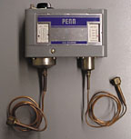
Low-pressure controls have been controlling box temperatures in freezers and refrigerators for many years. Figure 2 shows a combination low- and high-pressure control on a forced-air condensing unit.The low-pressure control is set to maintain box temperatures in the refrigerated case by setting the cut-out/cut-in and differential setpoints on the pressure control. The difference between the cut-in and the cut-out of the control is called the differential, as illustrated by the following equation:
(Cut-in) – (Cut-out) = Differential
For example, if the low-pressure control is set to cut the compressor out at 20 psi and back in at 35 psi, the differential would be 15 psi (35 psi - 20 psi). Table 1 is a chart to help the service technician set low-pressure controls for different fixtures and applications.

COMPRESSOR CYCLING DEVICES
Low-pressure controls can cycle the compressor on and off in response to a liquid line solenoid opening and closing in the liquid line of the refrigeration system. This type of control scheme is called an automatic pumpdown system.The thermostat in the refrigerated case controls the box temperature of the case. When the box temperature is satisfied, the box thermostat opens and de-energizes the liquid line solenoid. With the liquid line blocked, the compressor pumps the refrigerant to the high side of the system.
The low side of the system falls in pressure and the low-pressure control opens at a predetermined pressure, shutting the compressor off. The predetermined pressure is system dependent but is usually about 5 to 8 psi on refrigerated cases. (Cutting the compressor off at 0 psi is too hard on compressors because of the higher compression ratio at 0 psi.)
The pumpdown system uses the low-pressure control simply to cycle the compressor and not to control box temperature. The thermostat controls the box temperature. Figure 3 shows a schematic wiring diagram of an automatic pumpdown system. Figure 4 shows a point-to-point diagram of an automatic pumpdown system.

PRESSURE PROTECTION
Pressure controls can also be used as protective devices.Low-pressure controls can protect compressors from too low of a pressure situation in case of a coil freeze-up or lost refrigerant charge. Low-pressure controls can also protect some water chillers from freeze-ups.
High-pressure controls can protect compressors and system components from dangerously high-pressure situations by shutting the compressor off at certain elevated pressures.
Some high- and low-pressure controls have to be manually reset and some reset automatically.
NEW TECHNOLOGY
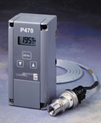
Figure 5 shows an electronic pressure control with a digital display. This electronic pressure control is a single-stage, on-off, single-pole, double-throw (spdt) output relay.Notice that the control has no capillary tubes to vibrate and cause wear and eventually refrigerant leaks. In many applications, manufacturers would have to put a silicone type of sealant between the coils of the capillary tubes to lessen vibration and try to prevent leaks.
Electronic pressure controls are designed for on/off control of direct- or pilot-duty hvacr loads based on system operating pressures. These controls are replacing a variety of electromechanical pressure controls.
The electronic pressure control features a large liquid crystal display (LCD) that show the magnitude of the pressure it senses along with other system status functions. During normal operation, the sensed pressure and other control status information is refreshed every 2 sec for the LCD. It also has a lockable, three-button touch pad that the technician can use to adjust setpoints in the programming mode. This lockout feature prevents building owners and/or the general public from tampering with the controller’s setpoints.
The same pressure control can be programmed to operate in one of three pressure ranges: 0 to 100 psi, 0 to 500 psi, and 50 to 750 psi. However, each of these operating ranges requires different transducers for proper operation.
Small jumpers also have to be repositioned when selecting different pressure ranges and unlocking the touch pad. The pressure control can also operate to open on either low or high pressure.
A flexible wiring harness connects the pressure transducer to the control. The wiring harness eliminates leak problems and is much more versatile with fewer constraints than capillary tubes. The transducer may be wired up to 100 ft away from the controller using three-wire shielded cable.
ANTI-SHORT CYCLE DELAY
The controller also has an anti-short cycle feature.There is a programmable minimum time that the equipment remains off before starting again. It may be programmed for 0 to 9 min in 1-min increments.
When the delay is activated, the LCD flashes the sensed pressure and gives the time remaining on the time delay. This added time-delay feature can prevent compressor overheating problems and also prevent starting relay and capacitor damage.
SECONDARY POINTS
The pressure control can establish a secondary set of cut-in and cut-out values. They are enabled when a circuit is closed between the binary input terminals.The LCD shows the primary (S1) or secondary (S2) setpoints, the sensed pressure in psi, and whether the control is set for opening on high or low pressure.
PRESSURE TRANSDUCER
The electronic pressure control uses a pressure transducer to sense pressure (Figure 5). The pressure transducer is mounted directly on the system and is designed for use in commercial refrigeration and air conditioning applications.The transducer is supplied with a constant 5-vdc supply voltage. The pressure transducer’s output voltage is an analog signal that varies 10% to 90% of the supply voltage. In other words, the output voltage varies from 0.5 to 4.5 vdc, depending on the magnitude of the pressure signal that it senses.
The output signal varies in direct linear proportion to the sensed pressure. The pressure transducer is available in several pressure ranges up to 750 psi and can handle all noncorrosive refrigerants, as well as ammonia.
One pressure transducer can be wired to up to four controls on applications where pressure can control different functions. Examples of these applications are a high-pressure control controlling condenser fan cycling and compressor protection.
Also, four low-pressure controls may be connected to a single pressure transducer on the common suction header of a parallel compressor rack to stage the compressors.
Tomczyk is a professor of hvacr at Ferris State University, Big Rapids, MI, and author of the book Troubleshooting and Servicing Modern Air Conditioning and Refrigeration Systems, published by ESCO Press. To order, call 800-726-9696.
Publication date: 07/02/2001


