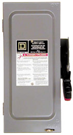
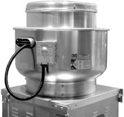
The switches are offered in a variety of shapes and sizes, and are classified under several different NEMA (National Electrical Manu-facturers Association) ratings. For design-build contractors, said Gullo, “Understanding the similarities and differences in disconnect switches will offer dollar savings to the contractor and his customers.”
The most common types are toggle and heavy-duty disconnects. Toggle switches are flipped on and off like a light switch, having a pushbutton or rotary-type handle, noted Gullo. Heavy-duty switches have a flip-arm knife-blade design. The switch may be visible or enclosed in a housing.
“The first decision is what type of enclosure you want,” he said. The enclosure selected depends upon the application, “whether the fan is being mounted outdoors or indoors, or if it’s a hazardous location.” Ratings range from NEMA 1 through 12 and are based on the enclosure’s ability to protect against moisture, dust, corrosion, or explosion.
NonHazardous Enclosures
The following are NEMA enclosures for nonhazardous locations.
Hazardous Enclosures
The following NEMA enclosures are for use in hazardous environments. Most of these environments require an explosion-resistant enclosure.“Explosion-resistant enclosures are designed to contain an explosion, not prevent one,” explained Gullo. They are constructed of cast iron or aluminum and provide limited access, making them undesirable as control system enclosures.
Enclosed heat-generating devices must not cause external surfaces to reach temperatures capable of igniting explosive gas-air mixtures in the surrounding atmosphere.
The hazardous class, division, and group specifications of these enclosures are designated by the NEC, Gullo said. The following are explanations of different class and division ratings.
Class I, Division 1 indicates that the disconnect can be operated in locations where flammable gases or vapors are, or may be, present under normal conditions, and which may ignite, explode, or cause failure of electrical equipment. These locations are called “normally hazardous.”
Class I, Division 2 indicates disconnects that are “not normally hazardous” because, unlike Division 1, they are normally contained within closed containers or a closed system, or are adjacent to Class I, Division 1 areas.
Class II, Division 1 covers locations where combustible dust is, or could be, present in the air under normal operating conditions sufficient to produce explosive or ignitable mixtures, or interfere with the normal operation of electrical equipment.
Class II, Division 2 covers locations where combustible dust is not normally present in the air in sufficient quantities to produce explosive or ignitable mixtures, and the dust is normally insufficient to interfere with the normal operation of electrical equipment.

Mounting Locations
The mounting location of a fan-mounted disconnect switch depends on its enclosure and the fan type. Locations, wiring terminology, etc., vary by manufacturer, pointed out Gullo, so for the purposes of an explanation, he described his company’s approach.In most cases for involving a NEMA 1 switch, the disconnect will be interior mounted on the fan in the following locations.
a. With wall housing — on inside of wall housing;
b. Without housing — on the fan panel (also when a wall collar is used).
For NEMA 3R, 4, 4X, and 12 switches, the disconnect will be mounted on the exterior in the following locations.
a. On the wall housing —special consideration; wall housing will not pass through the wall opening;
b. On the wall collar — special consideration; wall collar will not pass through the wall opening;
c. On the wall fan panel if no housing or collar is present.
For NEMA 7 and 9 switches, the disconnects are typically hard-piped and mounted next to the motor. On occasion, the location of the fan may not allow the typical mounting for the disconnect switch. In that case, the switch will be mounted in a different area “to avoid interference problems, such as with water piping or other ductwork,” Gullo said.
Also, a disconnect may be mounted remotely as needed to suit the particular application.

Wiring Terminology
When ordering disconnects, it is helpful to understand the wiring terminology, for example, loose; mounted and wired; or mounted, wired, and connected. If requested loose, the disconnect will not be mounted on the fan and the wiring will not be connected.Mounted and wired means the disconnect will be mounted on the unit and the wiring will be connected from the motor to the disconnect box. The wires at the disconnect will not be connected to the load side of the switch. The switch is shipped loose to allow external wiring to be connected in the disconnect enclosure without having to remove the switch. This is the standard method of wiring.
Mounted, wired, and connected applies when an extended wiring pigtail is specified. This means the disconnect will be mounted on the unit, the wiring will be run from the motor to the disconnect, and the wire will be connected to the load side of the switch. The pigtail is also connected to the supply side of the switch.
For explosion-proof switches, “Wiring is typically done in the field,” noted Gullo, “because codes vary from site to site.”

Disconnect Characteristics
In addition to enclosure, switch type, and mounting style, disconnect switches are also selected by several electrical/mechanical characteristics.One-Point Wiring
A convenient, time-saving option is one-point wiring, explained Gullo.“By factory-wiring the damper actuator, fan motor, and damper end switch to a single point, the installation of propeller fans is made faster and easier for the contractor.”
This option is available with NEMA 1 and 3R disconnects. If you need to use a different disconnect, consult the fan manufacturer.
For more information, Gullo can be reached at 715-355-2216; kendall.gullo@greenheck.com (e-mail).
Publication date: 07/30/2001


