Single- and three-phase alternating current (AC) motor speed can be controlled by controlling the frequency of the voltage coming to it.
Motor speed has a lot to do with the capacity of refrigeration compressors in refrigeration applications today. Air and water can also be controlled more closely with motor speed controls.
Because of this, many manufacturers of motors are working with electronic manufacturers and designers to pair up motors and electronic devices in order to efficiently and economically control the speed of a motor for capacity control.
This article will cover a device the industry is using for three-phase motor speed and capacity control called a variable-frequency drive (VFD).
The speed, or revolutions per minute (RPM), of a single-phase and three-phase alternating current motor is governed by the frequency of the voltage coming in the motor and number of poles of the motor. The governing equation is:
RPM = (Hz) x (60 sec/min)/(# of pole pairs)
Hertz (Hz) is the frequency of the voltage in cycles/second.

Notice that RPMs have units of revolutions/minute on one side of the equation but (Hz) has units in cycles/second on the other side of the equation. So, the conversion from seconds to minutes comes from multiplying by 60 seconds/minute.
What is left of the equation after this time conversion from minutes to seconds is that RPMs are governed by nothing but the frequency (Hz) and the number of poles. Notice that as the frequency increases, so do the RPMs. As the number of poles in the motor (denominator of equation) decreases, the RPMs also increase. It is much easier to change the frequency (Hz) of the voltage coming into the motor with electronics than it is to decrease the number of poles of the motor. This is where VFDs come into play.
The equation can be rewritten into the simpler form that follows:
RPM = (Hz) x (60 sec/min)/(# of poles/2)
By simply multiplying the numerator and denominator (top and bottom) of the equation by 2, the equation now becomes:
RPM = (Hz) x 120 (sec/min)/(# of poles)
Rewrite the equation again without the units and it becomes:
RPM = (Hz) x 120/(# of poles)
This is the format of the equation used in most books. However, do not get the 120 confused with voltage. It is not 120 volts! Voltage has nothing to do with the speed of an AC motor.
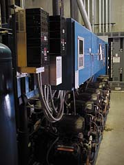
VFDs can control the speed of a motor by varying its frequency. Motor speed control can control temperature more accurately, thus increase comfort levels when delivering air or water, and at the same time can use electricity more efficiently. The VFDs control two of the compressors for very close capacity control.

OPERATION OF THE VFD
A VFD can consist of three separate electronic sections. The three electronic sections’ functions and their accompanying electronic components are:
Rectification: Figure 3 shows a circuit diagram of a three-phase VFD. Notice in Figure 3 that all three lines of the three-phase power go through diodes in the form of a bridge rectifier. The bridge circuit of diodes actually rectifies (changes) the three-phase AC voltage to pulsating direct current (DC). The output of this section is actually 12 half-wave pulses, which are electrically 60 degrees apart. Diodes let current pass only in one direction.
Filtering: The filtering section of the VFD simply makes the pulsating DC smoother or filters out its imperfections. These actually can be more than two capacitors wired in parallel with one another, but in series with the bridge rectifier and an inductor. The capacitance of capacitors adds when they are in parallel. There is synchronous discharging and charging of the capacitors with the three-phase input voltage. This makes a pure DC signal from the half-wave signal of the bridge rectifier. The capacitors in parallel filter the voltage wave and the inductor will filter the current wave.
Switching: The switching or transistor section of the VFD produces AC voltage at just the right frequency for motor speed control. There are two transistors for each output phase. The base or controlling part of the transistor is controlled by a preprogrammed microcomputer which fires the transistors at appropriate times in six steps.
Each set of transistors is connected to a positive and negative side of the filtered DC line. Thus, the motor can be controlled from about 60% to 125% of its rated speed (RPM). There are limitations to varying the speed of a motor. Heating and lubrication problems are two of them.
Tomczyk is a professor of HVACR at Ferris State University, Big Rapids, MI, and the author of Troubleshooting and Servicing Modern Air Conditioning & Refrigeration Systems, published by ESCO Press. To order, call 800-726-9696. Tomczyk can be reached at tomczykj@tucker-usa.com (e-mail).
Publication date: 08/05/2002


