In order to insure that valves perform up to these expectations, valve manufacturers generally specify or recommend that valves be installed per their instructions.
Small Valves
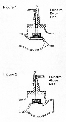
For small valves up to and including 8 inches, the recommended direction of refrigerant flow is from under the seat (see Figure 1). In this installation, the stem torque required to close the valve under system pressure is generally manageable.
Large Valves
For larger valves, 10 inches and above, this same flow direction can create a problem. If the valve is required to shut off against high system pressure, extremely large stem torque (closing force) is necessary to achieve tight shut-off. In fact, the required stem torque is so large that it cannot be obtained with a handwheel.Experience has proven that excessive force is required to close these large valves (10 inches or larger) when installed with the flow direction from under seat. To minimize this problem, large valves are designed and recommended to be installed so that when closed, the refrigerant pressure is acting from above the seat (i.e., stem side, see Figure 2). With the valve in the closed position, system pressure will then act on the stem disc from above. Consequently, most of the force required to achieve tight shut-off is provided by the system pressure. Valves installed with this orientation require only a relatively small stem torque to close the valve tight.
While system pressure from above the stem disc allows lower stem torques for closing, it conversely increases the stem torque required to open the valve. The reason is simply that the force being exerted by the system pressure on the stem disc must be overcome by the stem torque.
In order to reduce the force required to open these large valves and thus provide a smooth, easily opened valve, large valves incorporate an equilibrating stem disc design. This design is really a valve within a valve. The stem is designed so that it incorporates a small pilot valve. When the valve stem is rotated to open the large valve, it rises and opens bleed ports in the main stem disc. As these ports are opened, they allow high pressure refrigerant to bypass through the stem disc and equalize the pressure above and below the stem disc of the large valve (see Figure 3B). With the pressure equalized across the stem disc, the valve can be opened with little effort (see Figure 3C). The design of the equilibrating stem disc is such that the opening torque is reduced to 6 to 14 percent, depending on valve size, of the torque that would be required if this design was not used.

The second requirement for a shut-off valve is that it shall maintain tight shut-off under pressure. This raises the question of how long we can reasonably expect the valves to remain leak free.
Laboratory tests have been performed to determine this time factor. These tests indicate that when valves fitted with equilibrating stem discs are tightened per the specifications shown in Tables 1 and 2, we can expect the following:

Leak Testing
It is important to have a clear understanding of what is considered leak tight and how to perform leak testing. Tightness shall be determined by performing an air under water leak test.In order to test the valves, the valve should be capped and a capillary routed to a container of water or other suitable test media. With air pressure applied to the valve (pressure not to exceed values shown in Tables 1 and 2), observe the capillary outlet for the appearance of bubbles. Valves will be considered tight if after one hour there are no visible bubbles.
When testing valves equipped with an equilibrating stem disc, careful consideration must be given to the test pressures. The test pressures must be applied in such a manner and be of such a magnitude that the differential pressure (delta PV) across the valve being tested will not exceed the values shown in Tables 1 and 2. Thus, it may be necessary to apply back pressure (PBP) to the valves. The required back pressure can be determined by the simple formula:
delta PV = PT – PBP
PT = Test pressure (psi)
PBP = Applied back pressure (psi)
PV = Allowed differential pressure across the valve (see Tables 1 and 2)
Typical Installation
Figure 4 shows a typical installation consisting of a compressor with suction and discharge valves. It also shows a surge drum with a shut-off and a dead end valve for future plant expansion. Valves 1 and 2 have been arranged so that when closed, the system pressure will aid in achieving a tight seal (i.e., system pressure is applied on top of the stem disc). Under normal system operations, the refrigerant flow is from above the seat of the suction valve (2) and below the seat on the discharge valve (1).
To test valves 2 and 3, we can close the valves and pressurize the chamber created between them. In this case the test pressure is applied form above the seat disc of Valve 2 and should not exceed the values shown in Table 2. If a higher test pressure is required, then a back pressure must be applied above the seat of Valve 3 to prevent exceeding the values shown in Table 2.
Perhaps a simple example will help clarify this requirement.
Example:
Valve size: 10 inches
Test Pressure: 300 psi
For Valve 2, test pressure above stem disc, from Figure 4:
Allowable test pressure differential from Table 1 is 300 psi (delta PV).
Required Back Pressure PBP
delta PV = PT – PBP
300 = 300 - PBP
PBP = 0 (no back pressure required)
For Valve 3, test pressure below stem disc, from Figure 4:
Allowable test pressure differential from Table 2 is 220 psi (delta PV).
delta PV = PT – PBP
200 = 300 - PBP
PBP = 80 PSI
To avoid exceeding tight shut-off capabilities, we would need to apply 80 psi of back pressure to Valve 3.
Figure 5 shows the same system as Figure 4, except that Valve 3 has been repositioned. Now, when testing Valves 2 and 3, the test pressure is applied above the stem disc of each valve. Consequently, no back pressure will be required (example Valve 2 above).

Sometimes these large valves are installed at the end of a line in anticipation of future plant expansions. Dead end valves (such as shown as Valve 4 in Figure 5) should always be installed so that the pressure is applied above the stem disc. As an added precaution, a blind flange should be installed to protect the exposed end.
By now, it should be evident that special care must be exercised when installing and testing larger valves. It is important that the valves be installed, torqued, and tested per the manufacturer’s instructions. Remember, for the easiest installation and operation of valves 10 inches and larger, be sure you have valves fitted with equilibrating stem discs.
Reprinted from “Tech Tip 12” courtesy of Henry Technologies Inc. For more information, contact Henry Technologies at 701 South Main Street, Chatham, IL 62629; 800-323-4052; www.henrytech.com.
Publication date: 02/24/2003


