The motor calculations presented here apply to changing conditions of a blower motor when pulley adjustments are made. However, these calculations are useful wherever electric motors are used. These simple calculations can be used to solve motor installation and troubleshooting problems in a variety of applications. These motor formulas and related information are also basic to understanding energy consumption, power consumption by motor-driven devices, and the motor side of performing energy audits.
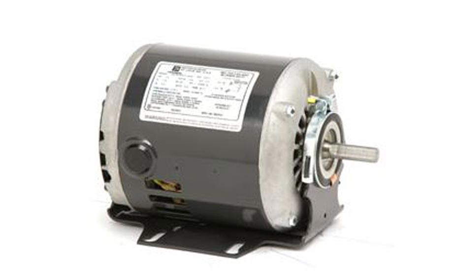
Fundamental to these useful calculations is some understanding of the information contained on a motor data plate.
Motor Data Plate Information Explained
Every motor has a metal nameplate or data plate listing the manufacturer, motor type, and electrical requirements for the motor.
Voltage
The voltage listed on the data plate is the design voltage the motor was made for. The motor may be operated at any voltage within 10 percent of the design voltage.
Full Load Amps (FLA)
This amperage is the current the motor will draw when the motor is loaded up to its rated horsepower. The motor will draw less than the listed FLA if the motor is operating at less than the rated horsepower. The motor will draw more than the rated FLA when it attempts to operate at more than the rated horsepower. Measuring the actual motor amperage and comparing it to the FLA is a good way to quickly tell if a motor is overloaded.
Locked Rotor Amps (LRA)
This amperage is the current the motor will draw when the motor is started and when the motor is attempting to start and run but is unable to do so for some reason such as mechanically stuck bearings. A rotor is said to be locked anytime the rotor is not rotating. This is normal on a motor that is off and ready to start. If a motor has bad bearings and cannot start, the proper terminology for that condition is to say the motor has stuck or frozen bearings. It would not be correct to say the motor has a locked rotor. All motors when off have locked rotors. The LRA rating of a motor is the most amperage the motor can draw under any condition.
Percent Efficiency
The rated percent efficiency for the motor is listed on most motors but not all. Motors that fail to state their efficiency probably have poor efficiency ratings. If the efficiency is not given, it can still be determined using basic math. Generally higher efficiency motors are those that use more metal in their construction and the metal is laminated and insulated between laminations to reduce eddy currents, which create heat. Heat in a motor is lost efficiency. The efficiency rating may be given as a percent such as 86 percent, or the same percentage may be listed as a decimal fraction like 0.86. When using the percent efficiency in a math formula, it must be used as a decimal fraction.
Power Factor
The power factor is also given as a decimal fraction and may be any number less than one. Common power factor (PF) ratings range from 0.70 to 0.98. The higher power factor is always more desirable.
The power factor is a number that tells to what extent the motor voltage and current are out of phase from one another. Unlike pure resistive circuits like electric heaters and incandescent lights, motors operate with strong magnetic fields present. The magnetic fields add a new element of magnetic resistance to the motor circuit, which throws the voltage and current out of phase with one another. When the voltage and current are not in phase, Ohm's law will not work unless the power factor is used to correct for this phase difference. The power factor listed on a motor is very useful to the technician when making motor horsepower and current calculations.
Service Factor
The service factor of a motor is a number that indicates how much more work a given motor can do beyond the rated horsepower. This is a safety factor and is not to be considered a part of the motor's normal useful horsepower. A motor may have no service factor whatsoever and thus has no safety factor in the event the motor becomes overloaded. A common service factor on motors is a SF of 1.15. This number multiplied times the rated horsepower gives the actual horsepower the motor could operate at in an emergency. For example; a 10 hp motor with a SF of 1.15 could actually provide service for a short time up to 11.5 hp. A motor with a high service factor is used in applications where the load may vary and may occasionally result in an unexpected overload in horsepower. Air conditioning systems often use motors with a SF rating of 1.15.
The service factor can also be multiplied times the FLA of the motor to give the absolute highest operating amperage the motor should be allowed to operate with. This use of the service factor is not recommended, as it is not completely reliable since it assumes the voltage the motor is getting is exactly correct. This is also a poor service practice because it encourages technicians to allow loading motors up into the safety zone the service factor provides.
Motor Horsepower Calculations
Some motors such as air conditioning and refrigeration compressor motors do not state their motor horsepower. A rule of thumb for air conditioning compressor motors is that there is one horsepower per ton. This rule will not work for applications other than comfort cooling air conditioning applications. The number of horsepower required to provide each ton of cooling varies with the suction pressure and head pressure. The higher the head pressure or the lower the suction pressure, the more motor horsepower is required to achieve a ton of cooling. Another way of stating it is that as the pressure difference between the suction and head pressures increases, the system tonnage decreases. This is why it is so important to keep condensers clean, evaporator air filters replaced, and airflow on both condensers and evaporators up to normal. Anything that increases head pressure or decreases suction pressure will decrease system capacity and at the same time increase operating costs.
The ability to determine actual motor operating horsepower on any motor, compressor motor, evaporator blower motor, or tower motor, is useful in troubleshooting problems or performing energy audits. Understanding the elements and process of basic motor horsepower calculations also increases awareness of energy consumption, motor operation, and potential problem areas.
Single-phase hp = E x I x Percent Efficiency x PF/746
The formula given above is used to determine the actual operating horsepower of any single-phase motor. If a motor such as a compressor motor does not state the motor horsepower, then this formula will also work to determine the rated or actual operating horsepower.
If the motor name/data plate information such as the rated voltage, rated FLA, rated efficiency, and listed power factor are placed in the formula, the resulting answer will be the rated horsepower.
The common use for this calculation is to determine the actual operating horsepower for a motor as it is presently being used. If a blower motor, for example, is going to get a drive pulley change, this formula will give the motor's actual operating horsepower prior to the change so the technician can tell if the motor has enough horsepower capacity available or if the motor must be changed. If the motor must be changed, this calculation also gives added information to help determine what new size motor will be necessary when the pulley is changed.
Example:
A single-phase blower motor has the following data plate information:
5 hp, 230 volts, FLA 20.72, Percent Efficiency 0.86, PF 0.91, SF 1.15
A technician measures the actual running amperage and voltage and finds the motor is getting 230 volts and is drawing 16 amps. The amperage is less than full load so the motor is not working at the 5 hp it is rated for. But what amount of work is it actually doing? Inserting actual measured values of voltage and amperage in the formula gives the answer.
Single-phase hp = E x I x Percent Efficiency x PF/746
Single-phase hp = 230 x 16 x 0.86 x 0.91/746
Single-phase hp = 2879.96/746
Single-phase hp = 3.86
The calculation shows the motor to be operating slightly more than one horsepower under the 5 hp rating.
A careful look at the single-phase horsepower formula reveals some useful information. The power law states that the voltage (E) times the amperage (I) gives the wattage or power consumption of a circuit. Therefore the horsepower formula includes both voltage and amperage. There are 746 watts in one horsepower, so every time a motor develops or uses 746 watts it has done one horsepower of work. Both wattage and horsepower are two ways of stating the same thing. This is why the 746 watts per horsepower is divided into the watts on the top of the formula.
Notice that the voltage times the amperage in the top of the formula not only gives the wattage, but the wattage is then multiplied times the percent efficiency and the power factor. The wattage gotten by multiplying the motor voltage times the motor amperage assumes that the motor is 100 percent efficient. Nothing is 100 percent efficient and motors are no exception. The efficiency of this motor is 86 percent, so the wattage is reduced to 86 percent of the calculated wattage by multiplying by 0.86. The reduced efficiency was lost in the form of heat and never produced the work in the form of rotational force which motors are made to do.
Obviously, the higher the efficiency the better and also the higher the initial cost to purchase. However, the energy savings from the higher efficiency may offset the higher initial cost. Remember, the power the utility bill reflects is all the power the motor uses, not just what the motor converted to useful rotational work but even the power lost to heat. A higher efficiency motor wastes less power to heat loss and may run less to get the same amount of work accomplished than a lower efficiency motor. Generally, it pays to purchase higher efficiency motors unless the motor is a small one. Small motors usually do not consume enough power to pay back the cost of the higher efficiency.
After correcting the motor wattage for the efficiency of the motor, the result is then corrected for the power factor of the motor by multiplying by the power factor rating listed on the motor data plate. The power factor was defined earlier as the degree that the voltage and current are out of phase with one another. A power factor less than one indicates that the two are not perfectly in phase, so the actual power the motor is working at is not what it could be if the voltage and amperage were perfectly in phase. Knowing and using the power factor and efficiency in motor calculations is vitally important if solid, useful numbers are to be attained.
Three-Phase Motor Calculations
Three-phase motors use the same calculation as was used for single-phase motors with one addition to the formula. Three-phase motors have three separate voltages each 120 degrees out of phase with one another. This is what gives the three-phase motor its superior starting and running power and eliminates the need for start capacitors and start relays to remove a starting winding as is often necessary with single-phase motors.
The three-phase motor is 73 percent more powerful than an equivalent motor using single-phase. The number 1.73 is added to the wattage side of the calculation to reflect this increase for three phases.
Three-phase hp = E x I x Percent Efficiency x PF x 1.73/746
This is the three-phase formula for determining motor horsepower including the addition of the 1.73 in its proper place. The 1.73 is the square root of the number 3 for the three phases.
In order to determine missing values of efficiency and/or power factor, the formula is the same as for single-phase except the 1.73 is included in the calculation.
Three-phase (Percent Efficiency/PF) = hp x 746/E x I x 1.73
Use this formula just like the single-phase version.
Relationships Between Rpm, Cfm, Pulley Dia., Horsepower, And Motor Amps
The technician who works with blowers and blower motors and makes adjustments to correct airflow quantities must understand the relationships between the various elements involved. A change in any one of the operating conditions will have an important effect on several others. Making adjustments without considering the effects of the adjustments may cause a blower motor burnout or may result in inefficient system operation. The purpose of making adjustments in the first place is to increase efficiency and provide for increased comfort at lowered operating costs as well as to avoid causing expensive system failures.
Relationship Of Rpm To Cfm
To increase cfm, the blower rpm must be increased. This is a directly proportional change. The percent of cfm change is proportional to the percent of rpm change. Since the rpm and cfm are directly proportional, the two are interchangeable in formulas. Where one is used, the other may be substituted.
Relationship Of Rpm And Cfm To Motor Pulley Size
To increase the rpm and cfm of the blower, the motor pulley size must be increased. This relationship is easy to remember as the motor pulley is always smaller than the blower pulley and, if the motor pulley were made the same size as the larger blower pulley, they would both go the same speed, which is the speed of the motor. Except for direct drive, no blower operates at the same speed as the motor.
The relationship of the rpm, cfm, and motor pulley is a directly proportional one. The rpm and cfm change by the same percentage as the motor pulley change.
Norm Christopherson is a senior training specialist with York International UPG in Norman, Okla. He is the author of a new book by PAL Publications titled HVAC Technician's Certification Exam Guide. He can be reached at norman.christopherson@york.com.
Publication date: 11/01/2004


