First, the reason we control head pressure (or more correctly, condenser capacity) is the need to maintain a minimum pressure differential across the orifice of the thermostatic expansion valve (TEV) so that the TEV's capacity can match the load.
In regions where ambient conditions vary widely, or where there are large load variations, head pressure control is an important issue with air-cooled condensers. Because of the importance of the issue, this article will examine some of its implications for the design and commissioning of systems.
There are three design parameters to be considered:
1. Day-night and summer-winter variations in temperature.
2. Day-night load variations (example: minimum compressor capacity).
3. Variations caused by other energy sources and atmospheric conditions (sun exposure, wind, etc.).
These variations can result in head pressure that is insufficient to ensure adequate flow into the system evaporator through the thermostatic expansion valve.

Control Strategies
Control strategies for air-cooled condensers include:A combination of on-off fan control and area control can also be used.
Here is an example of area control of a condenser surface.
Condenser capacity is given by the equation:
Qc = A x delta-t x u
In this equation:
Condenser Area Control And Load Variations
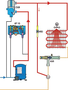
The effective surface area of the condenser can be controlled by using the head pressure or condenser pressure regulating valve (in our example system, a Danfoss type KVR), and by using a receiver pressure control valve (in our example system, a Danfoss type NRD). The NRD is a check valve with a decidedly stiff mainspring, and in addition has a second spring operating a damping device.
Valve Mounting Locations
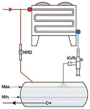
A receiver is essential in this strategy.Mount the condenser pressure regulating valve (KVR) in the discharge line between the compressor and the condenser. (See Figure 2.) Alternatively, it may be mounted in the line between the condenser and the receiver (drop leg). (See Figure 3.)
The receiver pressure control valve (NRD) must always be in a line between the discharge line and the receiver.
We can establish some strict guidelines for deciding the condenser pressure control valve (KVR) mounting location.
1. Mounting the condenser pressure regulating valve (KVR) in a position between the compressor and the condenser requires a larger valve because it has to be sized for hot gas capacity, and an extra check valve (Danfoss type NRV) has to be mounted in the drop leg between condenser and receiver to prevent refrigerant migration. (See Figure 2.)
This position of the condenser pressure regulating valve (KVR) is the best choice in very cold climates. It is also the preferred position when the system has a heat reclaim function.
2. When the condenser pressure regulating valve (KVR) is mounted between the condenser and the receiver, the valve needed is smaller because it is controlling liquid refrigerant. This mounting position is the best choice in temperate climates. (See Figure 3.)
Designing The System
Traditional wisdom bases selection of components for a refrigeration on the greatest expected load. So we have a generally accepted rule of thumb, but surprisingly, it often results in problems (most common source of trouble is large load variations). It is equally important to check whether the system will operate satisfactorily at low load conditions.Allowing for low load conditions is a part of the sizing procedure that should be mastered by system designers that want proper control under all load conditions.
When there is no condenser pressure regulating valve, load variation results in great swings in condensing pressure, and as evaporating pressure remains nearly constant, the pressure differential across the TEV will vary. This means that the capacity of the TEV, a function of the pressure differential across it, will change in response.
If the pressure differential across the TEV becomes too low, compressors may cut out on low pressure or begin to short-cycle, and there can be consequential product loss, or compressor damage, or both, all because low pressure differential across the TEV led to starvation of the evaporator.
It is important, then, to remember that the TEV's capacity is a function of the pressure differential across its orifice. Therefore, area control of condenser pressure with a condensing pressure regulating valve and a receiver pressure controlling check valve can be used in refrigeration systems where conditions require that the condensing pressure not drop below a specific minimum condenser pressure necessary to maintain proper TEV operation. This is true of systems with TEVs having either single or balanced port design.
To avoid receiver pressure going too low, the NRD valve will inject hot gas into the receiver, thus keeping receiver pressure at an acceptable level.

Receiver Pressure, Size
Without a receiver pressure valve (in our examples, the Danfoss NRD), load variations will result in large receiver pressure variations, and because the evaporating pressure remains almost constant, the pressure differential across the TEV will vary. To avoid receiver pressure going too low, the NRD valve will inject hot gas into the receiver, and so keep receiver pressure at an acceptable level.The receiver has to be sized so that it can cope with two worst-case conditions: (1) greatest system load, with maximum refrigerant level in the receiver (Figure 3); and (2) least load, with minimum refrigerant level in the receiver (Figure 5).
In the first instance (high receiver level), there must still be a gas space above the liquid in the receiver under greatest load conditions. It is also true that enough refrigerant must remain in the receiver under low load conditions for normal operation of the system.
Summer Ambient
Head pressure regulating valve (KVR) + receiver regulating valve (NRD), in high load mode (summer ambient conditions):Condensing pressure is higher than head pressure regulating valve (KVR) setting.
The differential pressure across the receiver pressure regulating valve (NRD) is less than 20.3 psi (1.4 bar). (See Figure 3.)
Winter Ambient
Head pressure regulating valve (KVR) + receiver regulating valve (NRD) in low load mode (winter ambient conditions):Condensing pressure is lower than the head pressure regulating valve (KVR) setting.
The differential pressure across the receiver pressure regulating valve (NRD) is more than 20.3 psi (1.4 bar). (See Figure 5.)
Receiver Volume
To calculate the receiver volume, first find:Extra Volume = Vmax – Vmin
Then use the relationship:
Condenser Volume = Normal Volume + Extra Volume
In this equation, extra volume is the total internal volume of the air-cooled condenser tubing, less the percentage active under light load low ambient conditions. The necessary information can be found in the manufacturer's data.
The maximum refrigerant charge variation in the receiver corresponds to the condenser's internal volume.
It is essential to size the receiver for this greatest volume plus head space. (See Figure 4.)
The NRD Receiver Pressure Valve
The NRD opens on differential pressure. As delta-p increases, the valve's opening increases (the valve is therefore a P-controller). (See Figure 7.) Dependent only on differential pressure, the valve is not adjustable. (See Figure 6.)The receiver pressure valve (NRD) will always "follow" the setting of the head pressure regulating valve (KVR) and the pressure changes in the system; it therefore "follows" the refrigeration system's operating pressure.

The KVR Head Pressure Regulating Valve
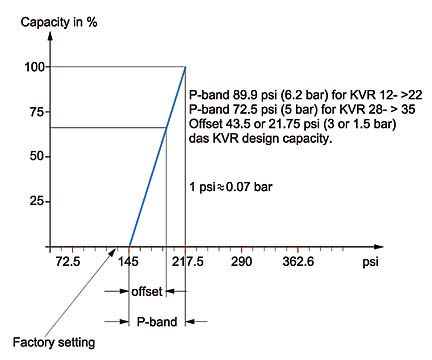
The KVR valve opens on inlet pressure. As inlet pressure in-creases, so does the valve opening (it is a P-controller). (See Figures 8 and 9.)The P-band is 89.9 psi (6.2 bar) for KVR sizes 12 to 22 and 72.5 psi (5.0 bar) for sizes 28 to 35.
We have chosen an offset of 43.5 psi (3.0 bar) for head pressure regulating valve (KVR) design capacity in this example. Here, the P-band is the pressure change from the beginning of opening to full open. The offset is the part of the P-band that represents the pressure increase needed above the opening pressure (the setting) to give the required capacity in relation to the condenser load. (See Figure 9.)
The setting of the head pressure regulating valve is dependent on:
Adjusting The KVR
When you adjust the head pressure regulating valve (KVR), there are three different scenarios:1. When the KVR is new and has the factory setting
2. When the KVR setting is not known and is adjusted using a pressure gauge
3. When the KVR setting is not known but is found again using a pressure gauge
Before we can start setting the valve, we have to find the minimum condensing pressure, which is:
The evaporator pressure (Pe) in psig + the total of all the pressure losses in the liquid line in + the minimum pressure differential across the TEV + the pressure drop across the evaporator distributor system.


Scenario No. 1
For a new valve, just installed, with the factory setting, we can adjust the head pressure regulating valve (KVR) in two ways: (1) by using a pressure gauge; and (2) by a procedure we will call "turn counting."We will first explain the "turn counting" procedure, then examine the gauge method in scenario No. 2.
Before we can adjust the head pressure regulating valve (KVR) we have to know:
The factory settings are:
The pressure change per turn of the adjustment stem:
For example, using the Danfoss TE2 thermostatic expansion valve:
Given R-22 at an evaporating temperature of -4 degrees F (-20 degrees C). This translates to an evaporating pressure of 21.75 psi (1.5 bar)
A TEV capacity range from 232 psig to 87 psig (16 to 6 bar) delta-p across the valve is acceptable.
The total of pressure drops in the liquid line is 7.25 psi (0.5 bar) (calculated).
The pressure drop in the distributor system is 14.5 psi (1 bar) (calculated).
The setting for the condensing pressure regulating valve (KVR), then, must be:
21.75 + 87 + 7.25 + 14.5 = 130.5 psi
(1.5 + 6 + 0.5 + 1 = 9 bar)
(opening pressure)
Adjustment:
130.5 – 145 = -14.5 psi
(9 – 10 bar = -1 bar)
Turns:
14.5 ÷ 21.75 psi
(1 ÷ 1.5 bar) =
0.67 turns counterclockwise
(for KVR sizes 28 to 35)
Turns:
14.5 ÷ 36.25 psi
(1 ÷ 2.5 bar) =
0.4 turns counterclockwise
(for KVR sizes 12 to 22)
With this setting, the valve will start to open at 130.5 psi (9 bar). Pressure at rated capacity will be 174 psi (12 bar). (In this example, the selected or "design" offset is 43.5 psi, or 3 bar.)
If the design offset is 21.75 psi (1.5 bar) instead, the opening pressure is still 130.5 psi (9 bar) but the fully open pressure will be only 152.3 psi (10.5 bar), resulting in a lower average condensing pressure over the course of a year, and a substantial energy saving. (See Figure 10.)

Scenario No. 2
A service situation where we don't know the setting of the condenser pressure regulating valve, so we will use a pressure gauge to make the adjustment. There are a number of unknowns, so we have a situation where we don't know either the opening pressure or the pressure at maximum load.Here's a summary of the situation confronting us when we set the pressure using a pressure gauge:
We find these system conditions:
The minimum load conditions:
But as is shown in Figure 11, we cannot calculate the setting, because we don't know the exact load conditions.

Scenario No. 3
Again we are in a service situation where we don't know the setting of the condenser pressure regulating valve, but we will find the setting so we can use the "turn counting procedure".When you want to find the opening pressure of the condenser pressure regulating valve (KVR), use the following procedure:
1. Turn off the compressors.
2. Adjust the condenser pressure regulating valve (KVR) to a high opening pressure, high enough that you can see on the pressure gauge when the valve starts to open. It may be necessary to short circuit the HP safety switch to prevent the compressors cutting out before you can reach the opening pressure.
3. Mount the pressure gauge on the condenser pressure regulating valve's access port.
4. Start the compressors.
5. Look at the pressure gauge, and you will be able to see the pressure where the valve begins to open (the opening pressure).
6. Now we can adjust by counting turns.
So, under any load conditions - summer, winter, wind, sun - we can get the correct setting for condenser pressure.
In condensing pressure control, it is important (1) to know the ambient conditions in order to select a proper location for the condenser pressure control valve; (2) to know the minimum condensing pressure for the system; (3) to choose the best adjustment method; and (4) to remember that it is possible to oversize the valve for reduced energy consumption and savings, which can continue to accrue throughout the life of the installation.
The "count revolution procedure" is the best way to adjust Danfoss condensing pressure regulation valves, or any condenser pressure regulator, for that matter, because by that method you will always know the opening pressure exactly.
The principal authors of this article are Jorgen Bargsteen Moller, manager of special projects, training, and education, Danfoss A/S (Nordborg, Denmark); and Max Robinson, Technical Communications, Danfoss Inc. (Baltimore).
Publication date: 06/14/2004


