One way of increasing the compressor’s performance (EER and capacity) is through vapor injection.
Vapor injection is essentially a two-stage refrigeration cycle that subcools liquid refrigerant going into the evaporator, and injects the resulting vapor at an intermediate pressure port into the compressor.
Some screw compressors are available with a vapor-injection port. What makes vapor injection possible is that, unlike reciprocating compressors, screw compressors can have ready access to intermediate pressure.
Vapor, injected at an intermediate pressure, allows the flexibility to control subcooling, which in turn allows for a greater increase in capacity and performance.
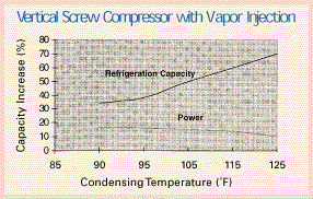
By using the feature of vapor injection (a.k.a., economizer), efficiency increases on the order of 25% to 60% can be realized. This is dependent on system operating parameters, and is accomplished without a proportional increase in power consumption or compressor displacement (see Figure 1, assuming –40°F saturated suction temperature).

DX Vs. Flash Tank
Vapor injection is accomplished with two different configurations, the direct expansion (DX) subcooler or a flash tank configuration.With direct expansion, liquid refrigerant is taken from the liquid line of the condenser through an expansion valve into a heat exchanger. The refrigerant boils at an intermediate pressure and the vapor is injected into the vapor-injection port.
The subcooled refrigerant may be the balance of the high-pressure liquid refrigerant from the condenser or an independent “side” load. The DX subcooler arrangement is straightforward (see Figure 2), but will exhibit normal heat exchanger losses.

The saturated liquid line forms a liquid seal at the bottom of the tank and is then expanded into the evaporator. The flash tank arrangement has the benefit of maximum possible system efficiency, but with the added complications of a flooded vessel and controls.
Vapor injection is just one of the readily available features on some screw compressors. Continuous research and development from screw compressor manufacturers allows greater improvements for the screw compressor packages of today.
Dan Bintz is an applications engineer with Hartford Compressors, Inc., 179 South St., West Hartford, Conn. 06110; 860-249-8671; Dbintz@hartfordcom pressors.com (e-mail).


