Now, Bob’s company has promoted him to help train a new employee, right out of a school specializing in HVAC, just like Bob was. Bob is now Tim’s Btu Buddy. Tim is anxious to travel with Bob. Tim realizes that he is right out of school, with the theory and lab work that he accomplished in school, but still needs help. He knows that he worked with many of the components of the systems in the school, under ideal conditions with good light and air conditioning. Now it is into the field, sometimes under the house with poor lighting, or out on the rooftop in the sun, where the real action is. He is naturally and normally reluctant, but he has Bob to help guide him.
Bob and Tim have been sent on a routine service contract call to a new customer. The system is a gas furnace with central air conditioning.
They met the new customer and went to the basement to look over the furnace and system. They changed the filter and oiled the fan motor. Tim went to the thermostat and caused the furnace to come on and they were looking at the burner when Tim said, “That gas flame doesn’t look right.”
Bob asked, “What do you see that doesn’t seem right to you?”
Tim said, “The flame has yellow tips. That isn’t what it is supposed to look like.”
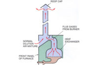
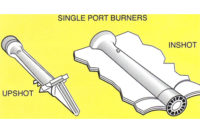
Bob said, “You are right. This is an older furnace with drilled port cast iron burners and air adjustments (Figure 1). Let’s see if we can adjust the primary air to the burner.”
Tim slightly opened the air shutters to the burners to give it more air and the flame started to lift off of the burner ports.
He then asked, “What is that all about? It is obvious that the flame doesn’t have enough air, but when you give it more air the flame rises.”
Bob said, “I think that we need to check the gas pressure. It seems that there must be too much gas flow for the burner. Can you tell me what the pressure to the burner manifold should be?”
Tim said, “In the lab at school we used 3.5 inches of water column for the manifold pressure for natural gas.”
Bob said, “That is correct. Turn off the furnace with the switch on the side of the furnace and connect this electronic manometer to the gauge port (Figure 2).”
Tim connected the electronic manometer to the gauge port and turned the furnace back on.
Tim then said, “The pressure shows 4.5 inches of water column. That is high. What can we do about it?”
Bob said, “The pressure regulator is right there, under that cover screw (Figure 3). Just remove the cap with a screw driver and the adjustment is under the cap. It will take a flat blade screwdriver or an Allen wrench.”
Tim asked, “How do I know which way to turn it?”
Bob answered, “Turning down (clockwise) on the screw will put more tension on the spring and cause the pressure to rise. Turning it out (counterclockwise) will reduce spring tension and reduce the pressure.”
Tim turned the screw counterclockwise about ½ turn and the pressure dropped a little. He turned it more until the pressure reduced to 3.5 inches of water column. Then he said, “I guess we will have to re-adjust the air to the burners.”
Bob said, “Yes, adjust them until there is no lifting of the burner flame off of the burner and no yellow tips.”
Tim asked, “What are the orange streaks in the gas flame? It is not yellow anywhere in the flame, just streaks of orange.”
Bob explained, “There are always particles of dust in the air. They burn up in the flame. I am going to tap on the burner manifold with this screwdriver. Watch what happens.”
“Wow,” Tim said. “That was really a show of orange. What happened?”
Bob said, “When I tapped on the manifold, a lot of dust particles, that you could not see, broke loose and burned in the flame.”
Tim said, “That was quite a show. I guess if someone were sweeping close by it would really affect the flame.”
Bob said, “Yes it would. Keep dust in mind any time you are adjusting a gas flame. You can’t really see dust in an oil burner flame because of its color.”
Tim asked, “What does inches of water column mean? We have no water here.”
Bob explained, “When pressures were being explored in the very early days, there was a need to compare various pressures. It was discovered that for very low pressures a water column could be used to measure pressure. It was discovered that a force of one pound per square inch would force water up a glass column and it was called a water manometer. It is a simple instrument that a person could make themselves. Figure 4 shows a U-tube water manometer connected to a gas valve. When disconnected, the water columns are level. When gas pressure is allowed to enter one side of the water column, it pushes that column down 1.75 inches and the other column rises 1.75 inches for a total of 3.5 inches. This is actually linear inches that can be measured with a ruler. It is a simple instrument but hard to maintain. If it is turned over, it will spill. If water is kept in the instrument, algae will grow in the water. Technicians have switched to electronic instruments calibrated and expressed in inches of water column.”
Tim then said, “It is nice to know where these terms come from and what they mean. There are probably many terms that are used that have a history that goes back a long ways. You mentioned that for low pressures water was used. What about higher pressures?”
Bob said, “For higher pressures, mercury (Hg) was used. It is much heavier than water, but is also a liquid. Remember when you studied pressures, the atmosphere, which is 14.69 pounds per square inch, will support a column of Hg 29.92 inches high. This is what an Hg barometer is used for. Electronic instruments have also been designed and calibrated to read in inches Hg. Listen to a weather report and the weather man will tell you the atmospheric pressure in inches Hg.”
They then finished the service call and moved on to the next call.
Publication date: 03/19/2012


