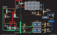
Using variable frequency drives (VFDs) to control the speed of a compressor can provide improved occupant comfort and quieter operation in air conditioning and heat pump applications. Tight temperature and humidity control can be achieved with a variable-capacity compressor driven by a VFD, and energy savings can also be realized by speeding or slowing the compressor down in response to the homeowner’s heating or cooling needs.
Let’s examine some motor equations to understand how this works.
The governing formula for the no-load (synchronous speed) of an alternating current (ac) motor in revolutions per minute (rpm) is as follows:
rpm = (ac frequency, or Hz) x (60 sec/min) / (No. of motor pole pairs)
Since rpm are in units of minutes (rev/min), and frequency is in units of seconds (cycles/sec), seconds are converted to minutes by multiplying by 60 seconds/minute. The equation can be rewritten as:
rpm = (Hz) x (60 sec/min) / (No. of motor poles/2)
If both the denominator and numerator of the above equation are then multiplied by 2 and written without units, the equation becomes:
rpm = (Hz) x (120) / (No. of motor poles)
This is the simplest form of the equation. The more poles the motor has, the slower the RPM. Conversely, the fewer poles the motor has, the faster the RPM. Also, as the electrical frequency decreases, the motor’s speed (rpm) will decrease, and, as frequency increases, the motor’s speed increases.
Since it’s easier to let electronic devices change the frequency of the voltage coming to a motor than it is to change the number of poles in the motor, VFDs have gained increasing popularity in the HVACR industry. Many refrigeration, air conditioning, and heat pump compressors today can employ electronic VFDs to vary the frequency feeding their electric motors.
VFDs work by converting the motor’s ac input to direct current (dc). From the direct current, the VFD will generate a simulated ac signal at varying frequencies (see Figure 1 above). The microprocessor controlling the VFD turns on and off the waveforms’ positive or negative half. A higher output voltage materializes from the power device remaining on longer. Conversely, the shorter the power device is on, the lower the output voltage will be. The switch frequency is the speed at which the power device switches on and off. More heat is generated in the power device as the switch frequency increases, but there is now more resolution and smoothness in the output waveform.
As mentioned earlier, motor speed is directly proportional to the electrical frequency used by the motor. Therefore, by varying the frequency to the compressor’s motor, the compressor’s motor speed (and, thus, the compressor capacity) can be controlled.
SHOUTING MATCHES
Using a VFD on a compressor is a very effective way of accurately matching compressor capacity to a load requirement. Matching a compressor’s capacity to the evaporator heat loading offers many advantages, such as:
• Better system cooling efficiency at part load;
• Less cycling on and off, which contributes to longer compressor life;
• Less fluctuation in evaporator temperatures and pressures;
• Gradual speed increases at start-up, which means less liquid refrigerant and oil return to the compressor; and
• Low starting currents, which eliminates the need for other starting devices.
OUT OF RANGE
Many modern VFDs can generate frequencies from 3.0 Hz to greater than 350 Hz, which is outside the operating range of modern refrigeration and air conditioning compressors. This is why compressor manufacturers will have minimum and maximum allowable frequencies and frequency ranges for their compressor motors when using a VFD.
Many of the operational characteristics of a compressor can be affected if a compressor motor does not operate within a certain frequency range. These may include:
• Compressor lubrication and cooling at low speeds;
• Proper oil pump operation;
• Compressor overheating;
• Increased electrical motor losses;
• Increased vibration; and
• Reed valve performance.
CHECK THE MANUAL
Always consult with the specific compressor manufacturer before using a VFD controller on any compressor.
VFDs are often controlled by an analog 4- to 20-mA signal; however, this depends on the type of VFD used. The control variable is usually suction pressure or indoor room temperature. Again, always consult with the VFD and compressor manufacturers for their control recommendations.
Publication date: 8/31/2015
Want more HVAC industry news and information? Join The NEWS on Facebook, Twitter, and LinkedIn today!


