
Every technician remembers the first time they encountered a ductless mini-split and the panic they felt inside. Not only do these units look unusual, but they behave to some extent differently from traditional split systems. Some troubleshooting tips to consider, which can resort to installation issues, include nevertheless design fundamentals. Understanding the following design aspects of mini-splits can assist the technician in determining what is happening inside the system as well as educate the next generation on the future of all-electric HVAC. For these tips, I sat down with Rachel Samala, owner of a mechanical HVAC company in San Diego, who has nearly a decade of experience in mini-split installation and service.
1. The motors can ramp up and down
When opening up a mini-split, the technician may be surprised to see that there is not much to see – just a control board and sensors everywhere. This is because the compressor and both fans are inverter-driven motors, meaning they use DC voltage to change speeds. On the basics of how this works, Samala explained, “AC line voltage reaches a rectifier which changes the voltage to DC. That DC voltage then goes through what is essentially a switch, the IGBT (insulated gate bi-polar transistor). The IGBT then feeds the compressor motor DC voltage in a way that mimics AC, thus creating the inverter action. This is what allows the compressor to soft-start and slowly ramp up and down.”
2. Mini-split vs. Multi-split vs. VRF.
By definition, all mini-splits are VRF (variable refrigerant flow), “meaning they have inverter compressors to vary the flow of refrigerant,” Samala elaborated. When a mini-split system has more than one indoor unit to one outdoor unit, these are referred to as multi-splits. Samala explained that technicians tend to differentiate highly sophisticated VRFs from minis and multi-splits in that the sophisticated systems can vary refrigerant flow between the evaporators to allow some units to heat and others to cool, through the use of numerous sensors and branch control boxes. One way to verify if the system is just a multi-split is to look at the number of pipes connected to the outdoor unit. If the outdoor unit has multiple pairs of pipes, then it is a multi-split, but if it has only two (high pressure and low pressure) or three pipes (for heat recovery), then it has at least one branch box inside connected to the indoor units.
Because multi-splits do not have the capability to vary refrigerant flow between the evaporators, all units must be calling for either heating or cooling.
3. These systems are “critical charge”.
Most manufacturers classify their mini-splits as “critical charge,” meaning the only approved method for charging these units is by weight, which differs from methods such as superheat, subcooling, or clear sight glass. The units arrive factory-charged, and manufacturers will specify how much refrigerant to add above a certain length of lineset which, for Mitsubishi, can be anywhere from 25 to 70 feet, so it is always recommended to check the installation manual for this as well as the minimum required lineset length.
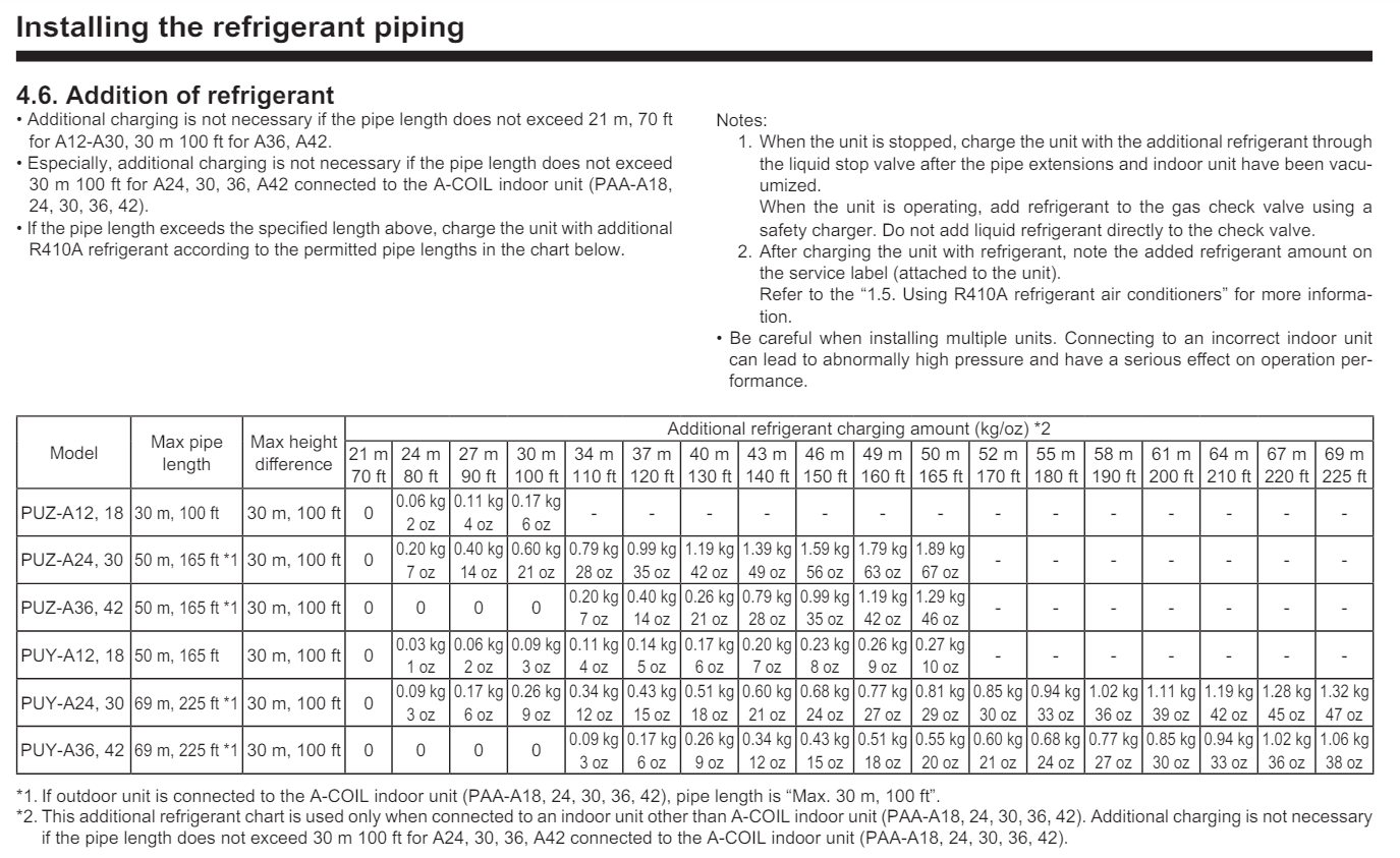
Click chart to enlarge
Figure 1: Charging chart for a typical, critically-charged Mitsubishi outdoor unit. (Courtesy of Lianna Schwalenberg)
4. The expansion valve is outside.
With these systems, the expansion valve is located in the outdoor unit. There are many logical reasons for this decision – such as noise and limited space. Because the evaporator is so small, mounting the valve directly onto the coil has the potential to more quickly flood the evaporator. As a consequence of the metering device being outside, both lines are low pressure in cooling, and both are high pressure in heating. When charging a unit in winter, it helps to pump the refrigerant into the high side using a recovery machine.
5. Superheat is normally low.
Sometimes mini-splits only have one service port, typically on the suction side, and it may be tempting to measure superheat. While this can be done, it is important to not be surprised that these units tend to run on very low superheat, usually 0-5°. These systems are designed to run at low superheat to maximize the efficiency of the small evaporator size, allowing more saturated refrigerant to fill the coil and absorb the heat load. The outdoor unit typically has at least one accumulator mounted on the suction side to protect the compressor from flooding.
6. Condensation management prevents water damage.
Both refrigerant lines should be insulated with foam to prevent condensation. If the insulation is not wrapped tight and touching the lines, moisture will build up inside the insulation and drip wherever possible. Linesets that run behind the unit and through places where the lines are colder than dew point are especially critical to wrap. To prevent water buildup, the condensate pump, if installed, is typically wired to cut power to the indoor unit temporarily when a float switch trips to give the pump time to operate and empty its reservoir.
7. Defrost control during heat mode.
Unlike a single-speed heat pump, an inverter mini-split is capable of staying in heat longer, not switching into defrost mode as frequently. This is accomplished by modulating the compressor and condenser fan and using more temperature sensors to make better decisions. Frost occurs when humidity in the air condenses on the lines and fins when the condenser coil temperature is below 32°. During defrost mode, the outdoor fan will shut off and the reversing valve will change to allow hot gas refrigerant to enter the condenser coil until a certain amount of time has passed and certain sensors are satisfied. Mini-splits typically have an electric base pan heater to make sure the melted water drips out of the unit.
8. Most indoor units are operated by wired or remote controllers.
Mini-split indoor units do not use the RGYW terminals with which technicians are most familiar. When asked why this is the case, Samala said, “Using standard thermostat wire and thermostats on inverters defeats the purpose of having an inverter system because inverters use DC voltage, which requires specific wiring and controllers.” If the system is controlled by a wired controller, it typically requires shielded 18/2 wire between the indoor head and the controller. If it is controlled wirelessly, a remote controller sends an infrared signal to a receiver at the indoor unit which converts the light data into electrical signals. Because of this, technicians can usually replace remotes without needing to program any data.
9. Flares are the most common leak point.
The common leak culprits are the flare connections, either because the installers did not tighten them to specifications and leak-tested, or the factory-flare of the lineset was botched. Many experienced installers, like Samala, recommend cutting out the factory flare on the lineset and making a new one as well as using a thread sealant to protect against leaks.
10. Leak-stop and dye are not recommended.
The principles of leak searching apply to mini-splits, just like any other system. If there is some refrigerant in the system, begin with an electronic leak detector, add nitrogen if needed. Pressurize and use soap bubbles as the next method. Change Schrader’s, hose gaskets, and apply thread sealant to gauges as necessary. Most mini-split leaks can be found and repaired without the use of dye or leak-stop. There are many wrong ways to add dye to a system, and some compressor manufacturers have not researched the effects of dye and leak-stop to properly approve or disapprove their uses.


