
While the need to refrigerate, freeze, and deep freeze will always be with us, it’s only been in recent years that scientists have determined a way to do that safely — and without harming the environment.
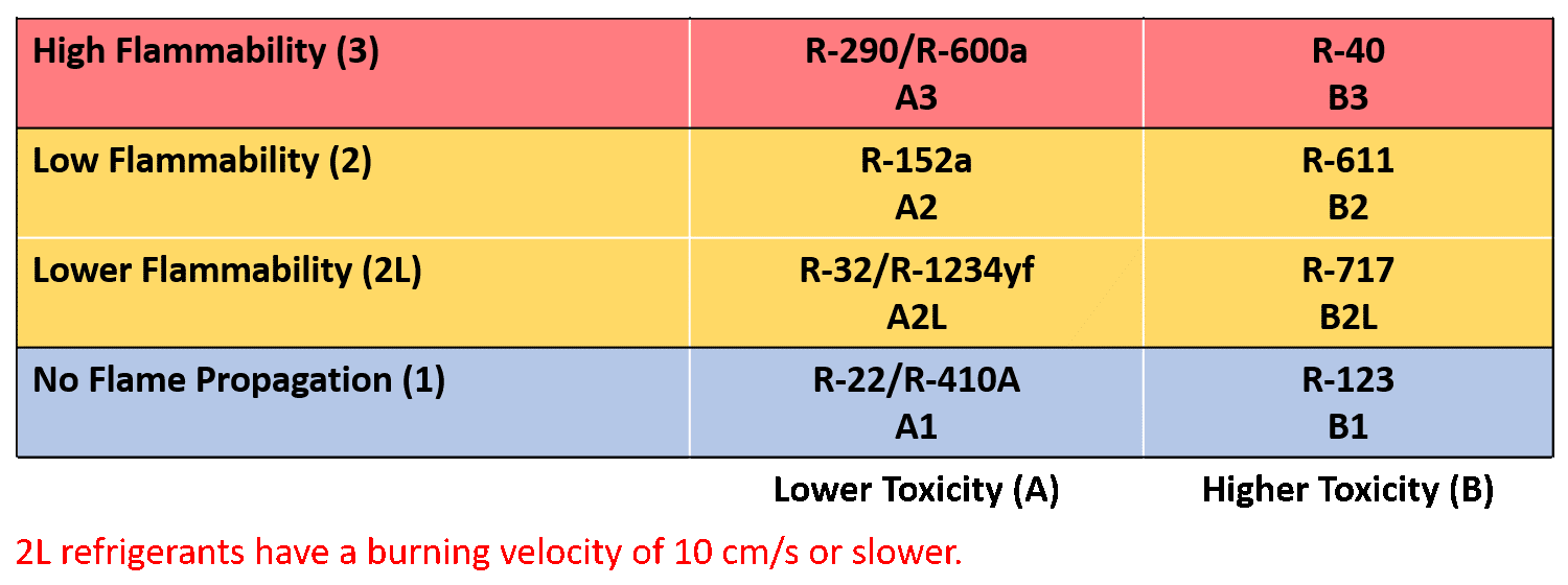
Beginning January 1, 2025, the Environmental Protection Agency (EPA) will prohibit refrigerants above 150 GWP in new stationary refrigeration equipment. That means that some of the more popular refrigerants, such as R-449A — with a GWP of 1,397 — and many other blends eventually will be phased out. They will be replaced with low-GWP refrigerants, including carbon dioxide (CO2), which has a GWP of 1, is non-toxic, and nonflammable, as well as A2Ls, which are also non-toxic but mildly flammable (see Figure 1).
Click to enlarge
FIGURE 1: ASHRAE safety classification of refrigerants. (Courtesy of Heatcraft)
CO2 Properties
Heavier than air, CO2 refrigerant (R-744) is a byproduct of the gas industry. A low-cost refrigerant that is easy to extract, CO2 carries an A1 safety classification from ASHRAE and also provides better heat transfer properties compared to HFCs. Existing naturally in the environment and with its GWP of 1, CO2 is also not likely to be phased out for another technology.
CO2 pipelines are also typically one to two sizes smaller than an HFC direct expansion (DX) system due to the higher density of CO2. For example, consider a 29.3 kW capacity medium-temperature compressor at 20°F saturated suction temperature (SST) and 95°F dry bulb (DB) ambient temperature. A CO2 compressor would have four to six times smaller displacement than an R-134a or R-407A compressor, and the CO2 system’s piping would be one to two sizes smaller compared to the piping used for the other refrigerants.
The challenge for many technicians lies in the high pressure associated with CO2. For example, at 88°F, the pressure of R-404A is 212 psia; with the denser CO2 at 87.6 °F, the pressure is 1,055 psig. Remember, the perfect gas law states that if a gas in a container is heated so that the temperature increases, then the pressure of the gas also will rise in proportion to its pressure-temperature relationship. Fortunately, engineers have a solution that manipulates temperature to control the high pressure: the CO2 booster system.
CO2 Booster System
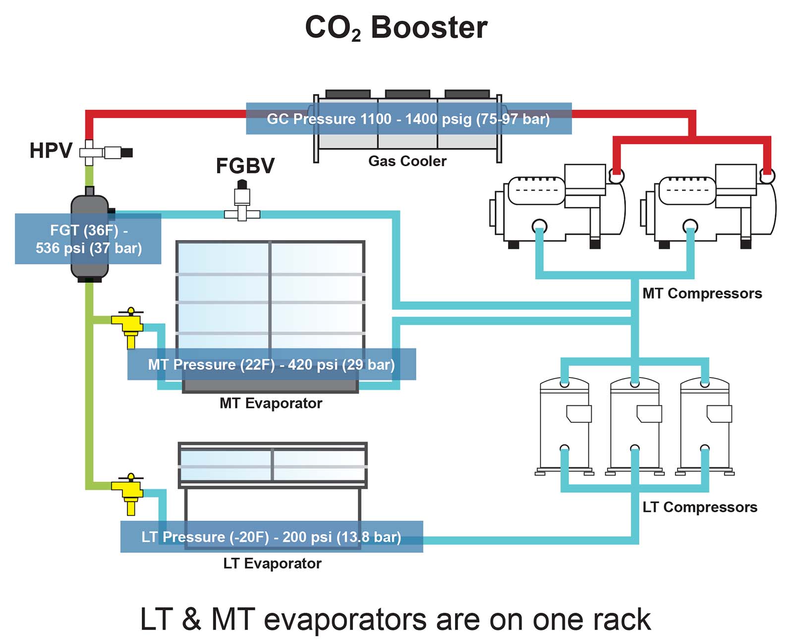
Note that in Figure 2, both pieces of equipment look similar. However, the R-404A DX uses a condenser, which changes the state of the vapor to a usable liquid refrigerant to feed the medium- and or low-temperature expansion devices. With the high pressure of CO2 — and the associated high temperature — a gas cooler is needed. That’s because in the transcritical high-pressure state ranging from 1,100 psig to 1,400 psig, the CO2 cannot condense into liquid CO2.
Click to enlarge
FIGURE 2: The R-404A DX uses a condenser, while the CO2 booster system uses a gas cooler. (Courtesy of Heatcraft)
A high-pressure valve is used to reduce the pressure and the corresponding temperature. That valve meters the CO2 into a flash tank, and the flash gas bypass valve (FGBV) at the top of the tank helps reduce the pressure inside the vessel. The target is about 536 psig, at which point the CO2 can condense into liquid CO2, providing cooling to both the low- and medium-temperature loads. Figure 2 shows that even with much higher pressure from the CO2 system, the same temperature loads can be achieved.
Unlike the HFC DX system, the CO2 booster system has two sets of compressors. A set of low-temperature compressors boosts the pressure that goes to the intake of the medium-temperature compressors. One set of compressors actually boosts the other, coming out of the low-temperature load of the evaporator outlet that is going to the suction manifold of the low-temperature compressor group. The compressors, in turn, lift the refrigerant pressure to match the outlet pressure of the FGBV and of the gas coming out of the medium-temperature load. The refrigerant being discharged by the medium-temperature compressor group will then feed the gas cooler inlet, completing the refrigeration cycle.
The booster system’s pressure and temperature monitoring devices are supported by a master controller, which regulates all system refrigerant valve positions. These components work as a team to determine the right amount of pressure in the flash tank, ensuring that enough liquid CO2 is available for the medium- and low-temperature loads.
Although the CO2 system may seem a bit more complicated than HFC DX systems, it is actually quite similar. In all cases, simply control the temperature to manage the pressure, and you will discover the significant benefits of CO2 refrigeration for both your customers and the planet.
CO2 Safety
Only authorized personnel and competent operators should perform maintenance or repairs on refrigeration systems. All staff working on this type of equipment should use personal protective equipment including gloves, glasses, and safety shoes. The safety instructions for working with CO2 are the same as they are for other refrigerants:
- Prevent liquid from reaching the compressor;
- Provide a pressure relief valve (PRV) for overpressure protection;
- Prevent excessive vibration;
- Ensure proper alignment of piping to prevent connection stress;
- Protect external surfaces from corrosion; and
- Take precautions to avoid refrigerant contact with skin due to the risk of frost or burn.


