Bob and Tim are driving to a new customer site where there is a complaint of the building not maintaining the correct temperature. The system is a 50-ton air cooled chiller mounted on the roof. (Figure 2) The weather is very hot, 97°F, and the indoor conditions are 78°F. The thermostat is set for 75°, and it is late afternoon.
They arrive and talk to the building manager who explains that he is getting complaints from all over the building.
Bob and Tim go to the roof through the roof hatch on the top floor and are walking around the chiller for a visual inspection. Tim then asks, “What should we be looking for?"
"The system certainly is running so that’s not the problem," Bob explained. "The problem seems to be that it can’t carry the load. Most buildings in our area are designed for a 95° day and it’s 97°. That might account for a little bit of temperature rise if the system were to be exactly to the load. If the building had an exact 50-ton load at 95°, it would be expected to lose ground above 95°, and the temperature would begin to rise in the building. However, most systems have at least a 10 percent cushion in the design sizing of the system, so I doubt that’s the problem. We want to look and make sure that the system is performing to its maximum ability because we’re in maximum temperature ranges.”
Tim asks, “Should I get the gauges and the electrical instruments?”
Bob replied, “Yes, I don’t think we will need the gauges because the system has gauges on it that are permanently installed. The ammeter will probably be needed to see if the compressors are pulling full load amperage.”
After Tim returns, they open the electrical panel where the compressor contactors are located. Then, they look at the nameplate and determine what the compressor amperage should be at full load. They amped each compressor and found they were running a little bit below full load amperage, so they checked the voltage to see if they were running high or low voltage. The voltage was running a little above normal, which would cause the amperage to become lower than normal.
"Look at the site glass going to the expansion device," Bob said. "It has a few bubbles in it. This could be one of two things: the liquid line dryer might be partially restricted or the unit is slightly under charged.”
“How can we tell the difference?" Tim asked.
Bob replied, “Get the temperature tester and let’s check the temperature across the filter dryer. If the filter dryer is partially plugged, there will be a temperature drop across the filter dryer. If there is a noticeable temperature drop, we will need to change the filter dryer element.”
They checked the temperature across the filter dryer and there was no drop in temperature; however, the liquid line was a little warmer than normal.
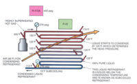
“This condenser should be able to condense refrigerant at approximately 25°F warmer than the ambient air temperature, which is 97°F," Bob explained. "Therefore the liquid condensing from the condenser should condense at about 122°F. (97+25=122) In other words, the liquid coming right off of the condenser should be at a temperature of about 122°F. The liquid should then pass through the subcooling circuit and be reduced by about 15° to 107°F. (122-15=107) The filter dryer is located after the sub cooling circuit, so the temperature at the filter dryer should be about 107°F and it is 122°F. That tells me that the subcooling circuit is not effective. Since there are bubbles in the site glass, it further verifies that there is not enough refrigerant in the system to fill the subcooling circuit, so this system is a little bit short of refrigerant”.
Tim asked, “What should we do next”?
Bob replied, “Go to the truck and get a cylinder of refrigerant, a set of gauges, and the electronic leak detector. We should do our leak detecting before we touch any of the service ports. Oftentimes, a previous technician will remove the gauges and not leak detect afterwards. If we just go in and put our gauges on, we may miss a leak at the gauge ports. So we will leak check the gauge ports and service valve covers before we do anything.”
When Tim returned with the supplies, he had an additional question. “Will charging the system to a full subcooling circuit help the capacity of the system?”
Bob explained, “For every degree of subcooling, we will get about 1 percent capacity. This system is rated at 50-tons at 95°F with a full subcooling circuit. So we can assume that this chiller is operating at about 45 tons of capacity with no sub cooling. When we fill the subcooler, we will get the full 50-tons out of the chiller, and that is probably going to be enough to bring the building temperature in line.”
They used the electronic leak detector, went over all of the fittings around the unit, and found two flare nuts with slight leaks. They verified it with slow blowing soap bubbles. They were able to tighten the flare nuts and stop the leaks. Then, they fastened their gauges and charged the system to 12° of subcooling. Afterwards, they rechecked the compressor amperage to find the amperage went up slightly, so they knew the compressors were working a little bit harder. Then, they went to talk to the building manager and explained that they had improved the system's operation by about 5-tons of capacity with their service call. They explained that while the system probably would not catch up by closing time today, by tomorrow it would start out at full capacity and should not lose any ground all day long, even though it was predicted to be another 97°F day.
“I remember the mention of subcooling while in school, but I would like for you to please explain to me again how it adds capacity to the system," Tim said.
Bob explained, “Every Btu of heat you remove from the condensing refrigerant gives the evaporator more capacity. If we furnish the expansion device with refrigerant at saturated temperature, we get a certain amount of capacity out of it. If we can cool the saturated liquid refrigerant to a temperature below saturation, we can get more capacity from the expansion device and evaporator. The way you lower the liquid temperature below saturation is to have an isolated circuit. Look at this diagram, (Figure 2) the liquid from the condenser drains into a small tank or reservoir at the bottom of the condenser. The liquid builds up in that container, and then liquid from the bottom of the container drains to a separate coil portion where the air from outdoors removes heat to a temperature below the condensing temperature, which is called subcooling. You can not subcool liquid refrigerant in the condenser because there is condensing taking place. Subcooling has to take place in a separate coil away from the condensing process. In this case, the condensing temperature was 122°F. We were able to remove about 15°F from the saturation temperature and lower the line temperature down to 107°, giving us more liquid line capacity.”
As they were putting up their tools Tim said, “Another day that I learned something. I am really impressed that you know what to do in almost every situation. I wonder if I will ever be to that point.”
“Yes, you will, and you will learn even more because you’re going to learn everything that I know, plus everything that you can add to it," Bob said. "A second-generation student always gains more knowledge than the generation before. You do have to remember a lot of these things to be able to apply and use them, but when you learn them the way we’re learning, you likely will never forget the lessons.”
Publication date: 7/23/2018
Want more HVAC industry news and information? Join The NEWS on Facebook, Twitter, and LinkedIn today!


