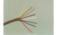
Bob and Tim are at a job where a technician from another company could not figure out the electrical, so he just put the panel back on the electrical compartment and left the job. It is a heat pump and the compressor wiring is all loose. They need to figure out how to wire it back and find out the problem. The homeowner said the original call to the other service company was because of ice build up on the outdoor coil.
Bob and Tim talked to the homeowner and explained that because the weather was cold and damp, ice buildup was expected on any heat pump in this kind of weather, but they would check the unit and see what was going on. The heat pump compressor was not running and the home was being heated with the auxiliary heat, so the first order of business was to get the heat pump operating.
They went outside and noticed the ice had melted from the outdoor unit due to an above freezing day. The compressor was not running; however, the fan was running. They looked at the compressor and discovered the wires to the compressor were all disconnected, and the ends were taped to make them safe.
“That explains why the compressor is not running, but why are the wires not connected?" Tim asked. "The technician must have been on some kind of trail, got lost, made it safe, and just pulled out. How do we know which wire goes to what terminal on the compressor?”
“I have seen this type of thing happen before," Bob said. "I think the technician removed the wiring looking for something, did not mark the wires, and could not figure out how to rewire it. The technician was probably embarrassed and just pulled out rather than look for help. We can tell which wire goes to which terminal by the unit wiring diagram. The question is, which terminal is common, run, and start. We will have to use an ohmmeter to determine that."
“What do we do?” Tim asked.
"The first things we need to do are check the compressor electrically and make sure it is safe to start; after making sure the compressor is safe to start, we need to reconnect it and see if it will start — the start assist (PTC) device may be defective; and when and if the compressor starts, we need to give the system a thorough check up to see why the technician was even doing what he was doing to cause him to disconnect the compressor,” Bob replied.
“How can we make sure the compressor is safe to start?” Tim asked.
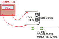
“We want to make sure that it is safe to apply power to the terminals," Bob said. "Use the Ohmmeter set on RX10K (10,000 Ohms). Second, fasten one lead to a good ground, scrape any scale or paint off the suction line, for example, and firmly hold the lead to the bare spot. Then, touch the other lead to one of the compressor terminals and record any reading. There should not be a reading. If there is a reading, the compressor has a ground circuit in the compressor. A circuit from the motor windings to ground.
"To illustrate how your meter works, you should be able to read a slight reading through your body if you hold one lead in each hand," Bob continued. "That is showing a slight circuit through your body. Your body has a high resistance, but a meter with an RX 10,000 scale will read through the body. When you hold the two leads apart in the air, you will get an infinity reading, or a resistance so high that it will not register on the meter. That is the kind of reading you want from a compressor motor to ground, infinity.”
They checked the motor for a ground circuit and it checked out good.
“We are going to use the next procedure for two functions," Bob said. "To determine that the windings are okay to apply power to, they must have a measurable resistance between the terminals before applying power. A short circuit between terminals would overload the circuit and trip a breaker. An open circuit means the winding is burned out, no circuit and current won’t flow. Next, is how to wire the disconnected wires to their correct terminals."
Bob explained, "You have to draw a diagram of the terminal arrangement looking straight into the terminal box. Now, label the terminals 1, 2, and 3. Now set your Ohm meter to RX1 and check the Ohms reading from 1 to 2 and write it down. Now check from 1 to 3 and write it down. Now check from 2 to 3 and write it down.”
Tim wrote it down as,
- 1 to 2, 2 Ohms;
- 1 to 3, 5 Ohms; and
- 2 to 3, 3 Ohms.
The largest reading was from 1 to 3, and would be the reading through both windings so that would be from 1 through common to 3. This tells you that the 2 terminal is the common terminal. (Figure 1)
“You have identified the “C” the common terminal as the number 2 terminal," Bob explained. "Now we know from process of deduction what the other 2 terminals are. The shortest winding with the least resistance is the run winding so terminal 2 to terminal 1 is the smallest resistance making the 1 terminal the “R” run terminal. The only terminal we have left is the “3” terminal and that makes it the start terminal. You can now take the red wire and put it on the run terminal, the white wire on the common terminal and the black wire on the start terminal.
“We need to check the start assist device, the PTC device (Figure 2)," Bob continued. "This device can be checked visually and with an ohmmeter at room temperature. It looks good visually. I have seen them fail, and usually you can see damage from the outside. This one seems good on the outside. Since the PTC is so cold from being outside, I think we will just try to start the compressor with an ammeter on the PTC circuit and it will either show current flow or not. If it doesn’t show current flow, we will replace it. You are now ready to start the compressor.”
Tim had an ammeter on the compressor circuit and on the PTC circuit. He then engaged the unit disconnect and the unit started normally, so they let it run.
They let the unit run for about 30 minutes while they changed the air filter and checked to see that all of the air registers were open. The unit seemed to be operating properly with an air discharge temperature (without the strip heat operating) of 103° F.
"Why did we check all of the air registers for air flow?” Tim asked.
“Some owners will shut some of the registers to save money," Bob replied. "That reduces the total air flow through the system, and it's not good for a heat pump. Reduced air flow will cause the head pressure to rise and lower the heat pump efficiency”.
After the system had operated for about 45 minutes, they put the system through a forced defrost and it operated correctly. They declared the system was good to go.
“I am not real clear about some of the motor check ups that we do," Tim said to Bob as they were leaving the job. "Could we get together and discuss other electrical checks that we do with motors?”
“That is a good idea," Bob said. "We could discuss motor winding short circuits and current readings. We will get together soon.”
To be continued next month.
Publication date: 12/24/2018
Want more HVAC industry news and information? Join The NEWS on Facebook, Twitter, and LinkedIn today!


